
Anti-theft bicycle

A bicycle and pedal technology, applied in the bicycle field, can solve the problem of inconvenient carrying of extra locks

Inactive Publication Date: 2014-02-12
CHONGQING TIANZHIDAO SCI & TECH DEV
View PDF0 Cites 6 Cited by
  • Summary
  • Abstract
  • Description
  • Claims
  • Application Information

AI Technical Summary

Problems solved by technology

[0004] The present invention intends to provide an anti-theft bicycle to solve the problem of inconvenient carrying of additional locks for bicycles in the prior art

Method used


Image

  • Anti-theft bicycle
  • Anti-theft bicycle

Examples


Embodiment Construction

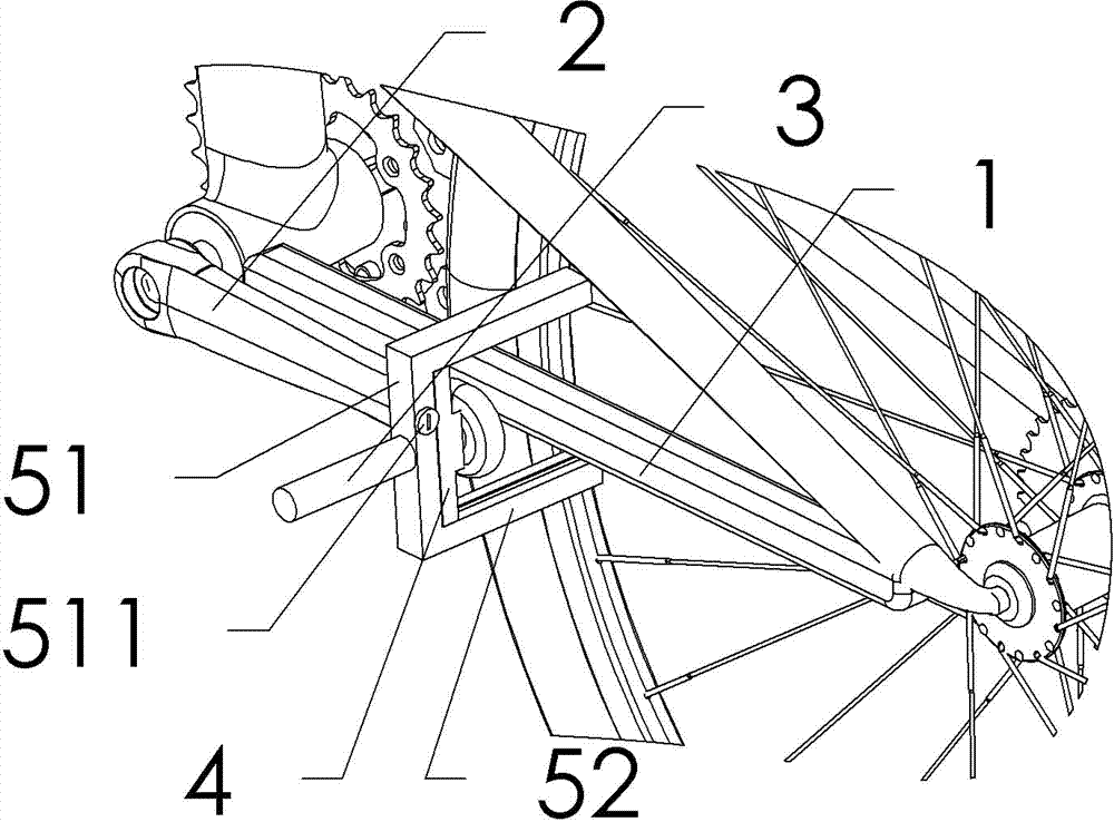
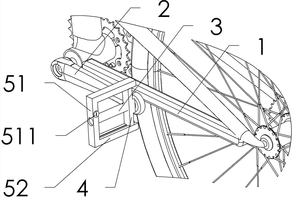
[0012] The reference signs in the drawings of the description include: flat fork 1, crank 2, pedal shaft 3, inner side 4, outer side 51, transverse side 52, lock 511.

[0013] The bicycle in this embodiment includes a flat fork for connecting the central shaft and the rear wheel shaft, and the central shaft is connected to a pedal shaft and a pedal at the free end of the crank.

[0014] riding status as figure 2 As shown, the shaft hole on the inner side is connected to the pedal shaft and cannot move axially. The overall C-shaped sliding locking side includes two transverse sides and the outer side and the slidable shaft hole is connected to the pedal shaft. The inner side The trapezoidal bosses at both ends of the side cooperate with the dovetail grooves on the inside of the two transverse sides, and the sliding locking side can slide towards the vehicle body under the constraints of the pedal shaft and the dovetail grooves. There is also a built-in lock on the outside edg...


PUM


Abstract

The invention discloses an anti-theft bicycle which solves the problem that an extra lockset of a bicycle in the prior art is inconvenient to carry. The anti-theft bicycle comprises pedals and a bottom fork. The anti-theft bicycle is characterized in that the pedals are provided with a lockset used for connecting the pedals and the bottom fork. The lockset can be a common chain lock or the like. The lockset can be fixed on the pedals in a twining mode and the like at ordinary times, and the lockset can be spread out and connected with the pedals and the bottom fork when needed, so locking of the bicycle can be achieved.

Description

technical field [0001] The present invention relates to a bicycle. Background technique [0002] The structure of a general bicycle includes a flat fork used to connect the central shaft and the rear wheel shaft. The central shaft is connected to the pedal shaft and the pedal at the free end of the crank. Drives the rear wheels to spin. [0003] Bicycle is the means of transportation that people are accustomed to. For safety considerations when parking bicycles, bicycles can be locked by additional locks to prevent theft, but additional locks need to be carried by the rider of the bicycle, causing a lot of inconvenience. Contents of the invention [0004] The present invention intends to provide an anti-theft bicycle to solve the problem of inconvenient carrying of additional locks for bicycles in the prior art. [0005] The anti-theft bicycle in this solution includes a pedal and a flat fork, and is characterized in that the pedal is provided with a lock for connecting ...

Claims


Application Information

Patent Timeline
IPC IPC(8): B62H5/10
Inventor 姜静慧
Owner CHONGQING TIANZHIDAO SCI & TECH DEV
Learn More