
Hydrological flood monitoring cableway buoy positioning automatic putting method and device

A buoy and flood measurement technology, which is applied to measurement devices, buoys, motor vehicles, etc., can solve problems such as inability to accurately and quickly test water flow velocity, difficult buoy vertical line, positioning, etc., and achieve the effect of convenient and quick measurement of flow velocity.

Inactive Publication Date: 2014-02-12
郗腾来
View PDF8 Cites 6 Cited by
  • Summary
  • Abstract
  • Description
  • Claims
  • Application Information

AI Technical Summary

Problems solved by technology

[0004] In order to overcome the shortcomings of the existing cableway flood measuring instrument, which is affected by the entanglement of aquatic plants, the rotating rotor cannot accurately and quickly measure the water flow velocity, many bridge casting buoys do not have bridge conditions, and it is difficult to locate the vertical line of the buoy. The present invention provides a hydrological The method and device for automatically launching the buoy position of the flood measuring cableway make the flow rate of the flood test unaffected by water, weeds and debris in the water flow, as well as dark and daylight and thunder and lightning weather. Putting in the vertical position, it is convenient and quick to measure the flow rate, and it will save valuable time for emergency rescue and disaster relief dispatching

Method used


Image

  • Hydrological flood monitoring cableway buoy positioning automatic putting method and device
  • Hydrological flood monitoring cableway buoy positioning automatic putting method and device

Examples


Embodiment Construction

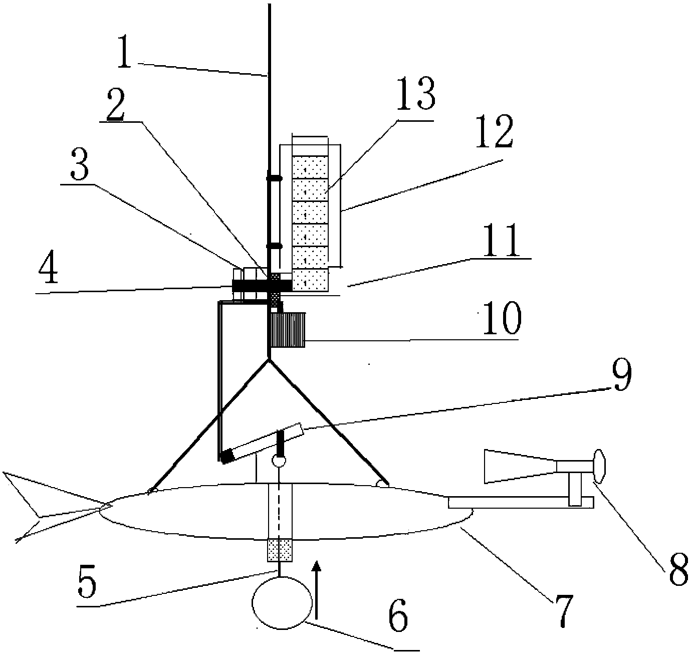
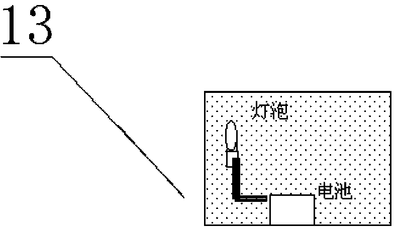
[0015] Now with reference to the accompanying drawings, the description is as follows in conjunction with the embodiments: a method and device for automatically launching the location of a hydrological flood measuring cable buoy according to the present invention, figure 1 Among them, there are slings 1 hanging lead fish 7, battery 10 and buoy storage box 12 on the steel cable of the flood measuring cableway, there is a float 6 below the lead fish 7, and the float guide rod 5 connected with the float 6 passes through Through the belly guide hole of the lead fish 7, the mercury switch 9 arranged on the top of the lead fish 7 is jacked up, so that the battery 10 and the electromagnet 2 on the buoy storage box 12 are connected, and the buoy guide rod 4 on the electromagnet 2 is displaced. The action of throwing a buoy 13 at the bottom in the buoy storage box 12 into the water surface can be completed. After putting in the vertical line of a section, lift the lead fish 7, the floa...


PUM


Abstract

The invention provides a hydrological flood monitoring cableway buoy positioning automatic putting method and a hydrological flood monitoring cableway buoy positioning automatic putting device. On the existing hydrological cableway, a storage battery and a buoy storage box are hung, a plurality of buoys are arranged in the buoy storage box in an overlapped way, a buoy outlet is formed under the box body, an electric magnet is arranged on the box wall, a displacement iron core of the electric magnet is connected with a buoy conducting rod, the electric magnet is conducted with a power supply of the storage battery through a mercury switch, a floating ball is arranged under a fish lead, a floating ball guide rod upwards penetrates through a guide hole formed in the belly part of the fish lead to be connected with one end of a mercury switch body, the fish lead falls down, the floating ball contacts with water, and the floating ball guide rod upwards moves, so that mercury in the mercury switch flows to the other end, the electric magnet and the power supply of the storage battery are conducted, the buoy guide rod moves, and one buoy arranged at the bottom of the buoy storage box is guided out of the water surface. When the fish lead is lifted up, the floating ball falls down under the gravity effect, the floating ball guide rod is linked with the mercury switch to cutoff the power, the buoy guide rod returns the original position under the effect of a reset spring, and the next buoy falls down to a position to be released under the gravity effect.

Description

technical field [0001] The invention relates to a river flood hydrological measurement method and device, in particular to a hydrological flood measurement cableway buoy positioning automatic release device installed on the existing hydrological cableway facilities. [0002] Background technique [0003] At present, most of the flood flow tests in natural river hydrological surveys in my country still use the cable current meter method for measurement, that is, the lead fish is hung on the cable, the current meter is installed on the lead fish, and the rotor of the current meter rotates under the action of the water flow. The rotor rotates a certain number of revolutions to connect the contacts once, and transmits the wireless signal to the receiving device on the shore, and automatically or manually calculates the speed of the water flow by timing and counting the number of revolutions. However, since there are more and more aquatic plants and sundries in rivers, the rotor ...

Claims


Application Information

Patent Timeline
IPC IPC(8): B63B22/00G01P5/18
Inventor 陈国浩孔舒牛淼赵晓旭张凌东王红岩高超李平张振成朱新庆其他发明人请求不公开姓名
Owner 郗腾来
Learn More