Detachable helicopter landing platform

A technology for helicopters and platforms is applied in the field of detachable helicopter docking platforms, which can solve the problems of labor and time-consuming, the platform cannot be disassembled, and it is not conducive to the large-scale utilization of helicopters.

Inactive Publication Date: 2014-02-12
许春雷
View PDF6 Cites 18 Cited by
  • Summary
  • Abstract
  • Description
  • Claims
  • Application Information

AI Technical Summary

Problems solved by technology

[0004] Because the traditional helicopter docking platform is mainly constructed with a large area of ​​concrete, it is not only labor-intensive and time-consuming, but also not conducive to emergency landing during rescue. After use, the platform cannot be disassembled, resulting in great waste
Therefore, the prior art is mainly aimed at transforming the landing gear of the helicopter itself, but the transforming of the landing gear of the helicopter will inevitably have an impact on the body structure, which is unfavorable for the large-scale utilization of the existing helicopter

Method used


Image

  • Detachable helicopter landing platform
  • Detachable helicopter landing platform
  • Detachable helicopter landing platform

Examples


Embodiment 1

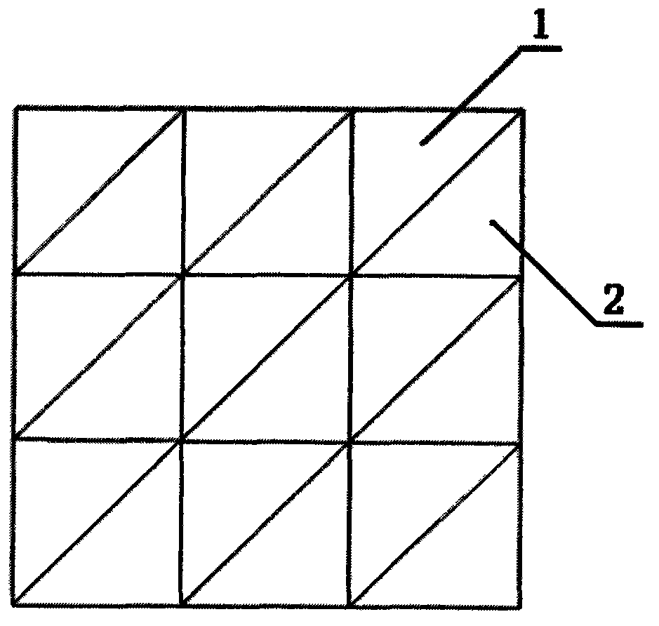
[0024] like figure 1 and Figure 4 As shown, the schematic diagram of the helicopter docking platform after the splicing of multiple substrates is completed, wherein any substrates are installed and spliced ​​through the engaging grooves or protrusions on the sidelines, and the engaging grooves and protrusions are fixed by one or more Screws strengthen the fixation. For example, at the joint between the substrate 1 and the substrate 2, an engaging groove 4 is provided on the edge of the substrate 1, and a protrusion 5 is provided on the edge of the substrate 2. Through the engaging groove 4 of the substrate 1 and the connection between the substrate 2 The protrusion 5 is installed to splice the substrate 1 and the substrate 2; and so on. Of course, the invention is not limited thereto, and the splicing can be completed as long as the edge lines of two adjacent spliced ​​substrates are respectively provided with engaging grooves and protrusions.

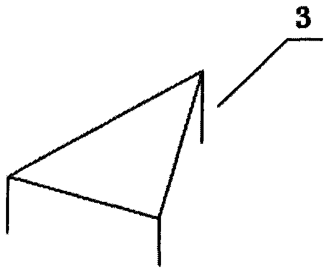
[0025] like figure 2 As sh...

Embodiment 2

[0035] like Figure 5 As shown, the lower supporting portion of the engaging groove 4 is provided with an installation angle θ. So that during installation, the protrusion 5 can be quickly extended into the groove with the help of other mechanical devices, and the position of the protrusion can be roughly fixed, and then the supporting legs can be further fine-tuned, and finally the protrusion can be fixed with screws. Through this design, splicing between substrates can be performed conveniently and quickly.

[0036] Further, the installation angle θ is preferably not greater than 5 degrees. In this way, even if there is a slight offset between the substrates, it can be ensured that the platform meets the plane requirements for the helicopter to dock, that is, the slope is not greater than 5 degrees.

[0037] The docking platform of the present invention has the advantages of simple structure, convenient installation and easy manufacture, and can realize docking of helicopt...


PUM


Abstract

The invention provides a detachable helicopter landing platform. The detachable helicopter landing platform is formed by splicing a plurality of triangular base plates. Telescopic supporting legs are arranged at three vertex angles of each base plate, and snapping grooves or protrusions are arranged on three edge lines of the base plates, the adjacent spliced base plates are mounted and spliced through the snapping grooves and the protrusions, and the snapping grooves and the protrusions are strengthened and fixed through one or more fixing screws. The platform has the advantages of being simple in structure, convenient to mount and easy to manufacture, and helicopters can be landed on uneven earth surfaces.

Description

technical field [0001] The invention relates to a helicopter docking platform, in particular to a detachable helicopter docking platform which can be freely built on any uneven ground. Background technique [0002] Helicopters have the characteristics of being able to take off and land vertically and hover in the air, can lift goods or rescue people in distress through external hanging methods, and have strong military and civilian versatility. life is closely related. Especially in emergency rescue, helicopters have played a huge and even unique role, which has attracted great attention. [0003] However, domestic helicopters are mostly designed to be parked on the ground. In order to ensure the safe landing of the helicopter, the parking slope cannot be greater than 5 degrees. In the "Wenchuan" earthquake, the uneven ground seriously restricted the rescue capability of helicopters. [0004] Because the traditional helicopter docking platform is mainly constructed with a...

Claims


Application Information

Patent Timeline
Patent Type & Authority Applications(China)
IPC IPC(8): E01F3/00
Inventor 许春雷
Owner 许春雷
Why Eureka
Try Eureka