Life saving device in high building
A technology for escape devices and high-rise buildings, applied in the field of high-rise escape devices, to achieve the effects of a stable and reliable descent process, increased escape efficiency, and reduced friction
- Summary
- Abstract
- Description
- Claims
- Application Information
AI Technical Summary
Problems solved by technology
Method used
Image
Examples
Embodiment 1
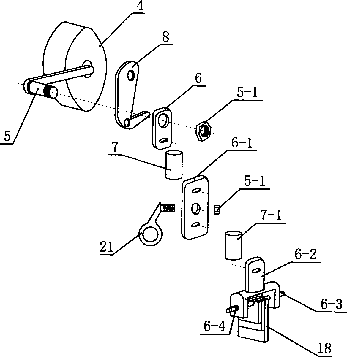
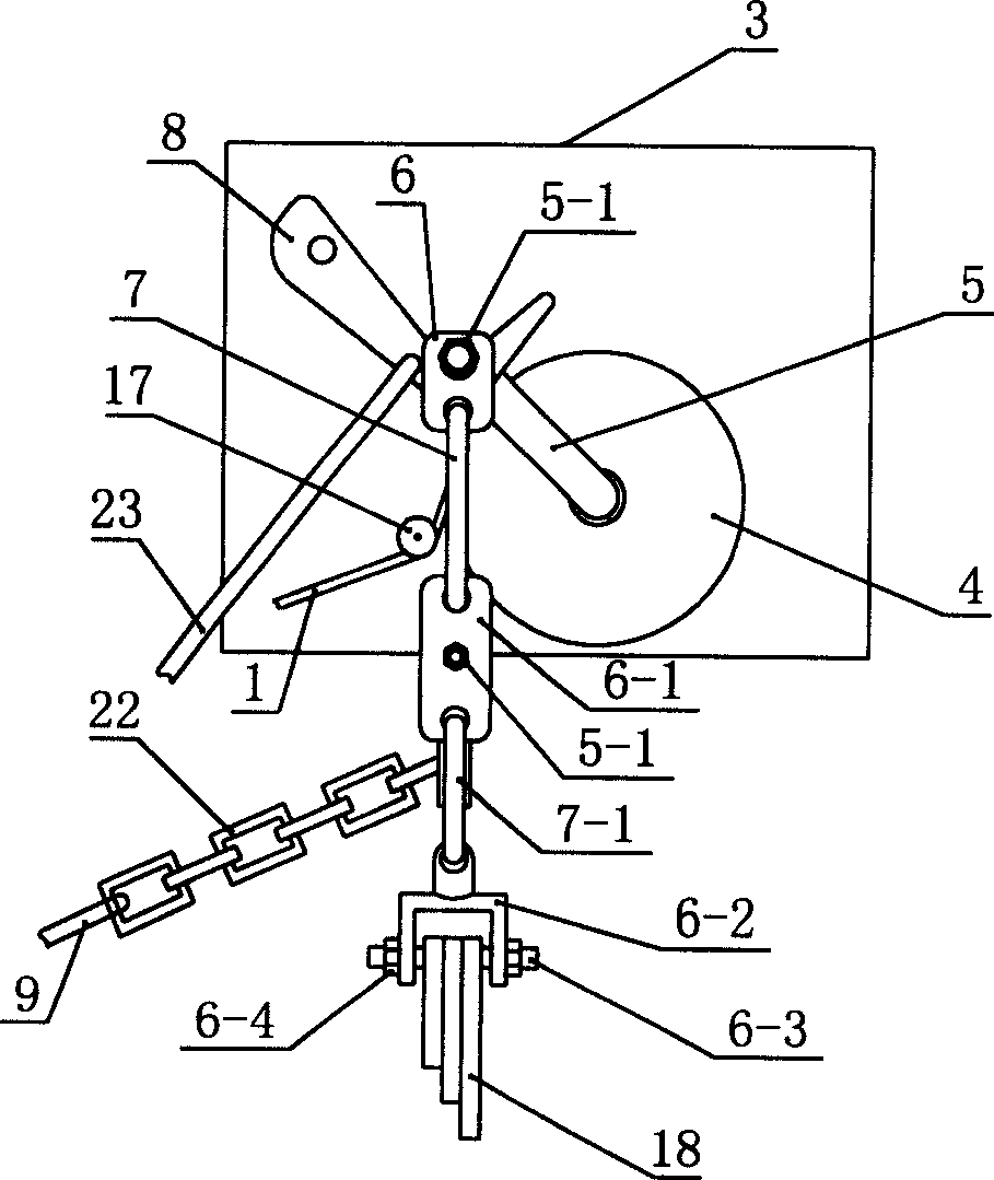
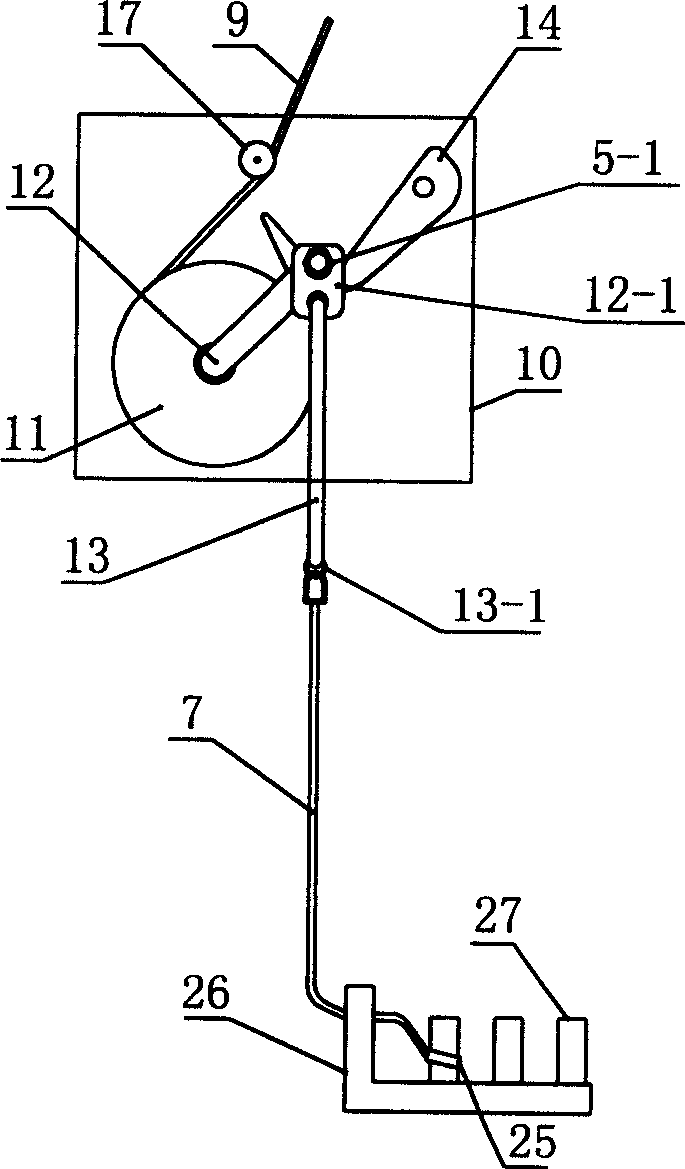
[0034] Example 1 as Figure 7 Shown, the present invention comprises descending rope 1, is located at the hook 2 of descending rope 1 lower end, and hanging basket 20 is hooked on the hook 2. Hanging basket 20 structure such as Figure 11 and 12 As shown, the side of the hanging basket 20 against the wall is provided with a triangular boss 24 with two slopes. The pulley frame 15 on the window wall is wound on the slow-down device, and the slow-down device is positioned at the box body 19 that is fixed in the house near the window wall, and the bottom surface of the box body has a door 19-1, and the side wall of the box body also has a door (not shown).
[0035] Triangular boss 24 such as Figure 11 and 12 As shown, when the hanging basket encounters an obstacle protruding from the wall such as the window sill during the process of descending or ascending, the two slopes of the triangular boss are used as a transition to pass smoothly. Such as Figure 9 , 10 Shown, pull...
Embodiment 2
[0039] Example 2 as Figure 8 As shown, the difference between Embodiment 2 and Embodiment 1 is that there is no box body 19, the lower end of the support 3 has a roller 3-1, and there is a brake device on the support. , all the other structures are the same as in Example 1.
[0040] bracket 3 as Figure 4 As shown, the braking device is located at the lower part of the bracket 3, including a "V" shaped piece 3-2 pivotally connected to the lower end of the bracket, one end of the "V" shaped piece is hinged on the horizontal connecting rod 3-3, and the horizontal connecting rod 3-3 is forward Protrude beyond the bracket 3.
[0041] When in use, first push the bracket 3 to the edge of the window, when the bracket is close to the window, if Figure 5 , 6 As shown, the horizontal connecting rod 3-3 protruding from the bracket 3 pushes against the wall under the window sill to retreat, driving the hinged "V" shaped piece 3-2 to rotate, and the bottom surface of the "V" shaped p...
PUM
 Abstract
Description
Claims
Application Information
 - R&D
- Intellectual Property
- Life Sciences
- Materials
- Tech Scout
- Unparalleled Data Quality
- Higher Quality Content
- 60% Fewer Hallucinations
Browse by: Latest US Patents, China's latest patents, Technical Efficacy Thesaurus, Application Domain, Technology Topic, Popular Technical Reports.
© 2025 PatSnap. All rights reserved.Legal|Privacy policy|Modern Slavery Act Transparency Statement|Sitemap|About US| Contact US: help@patsnap.com


