Sedimentation support for bridge

A technology of bearings and bridges, applied in bridges, bridge parts, bridge construction, etc., can solve the problems of increased maintenance costs, many supporting machines, and long operating cycles, achieving significant economic and social benefits, and timely road surface smoothness indicators , the effect of simple disposal method

Inactive Publication Date: 2008-08-27
郝贤成
View PDF0 Cites 12 Cited by
  • Summary
  • Abstract
  • Description
  • Claims
  • Application Information

AI Technical Summary

Problems solved by technology

[0003] 1. When it is necessary to restore the overall design line shape and flatness index of the road surface, it is necessary to subsidize and raise the oil layer in a large area on the road surface other than the bridgehead height difference (staggered platform), resulting in a sound road surface and unnecessary repairs, which will increase The number of projects is reduced, the maintenance cost is increased, and serious waste is formed
[0004] 2. When subsidizing and raising the road surface oil layer within a short distance outside the bridge head, it can only play the role of smoothing the local gentle slope. Although the cost is saved, the treatment effect is poor, and the road surface flatness index required by driving cannot be met.
[0005] 3. The construction of asphalt mixture has complex procedures, strong seasonality, high cost, heavy pollution, many supporting machinery, and long operation cycle
"Four liang of pig iron moving furnaces" is a serious waste of resources and does not meet the "timely, effective, advanced and economical" road surface disease treatment requirements stipulated in the "Technical Specifications for Highway Maintenance"

Method used


Image

  • Sedimentation support for bridge

Examples


Embodiment Construction

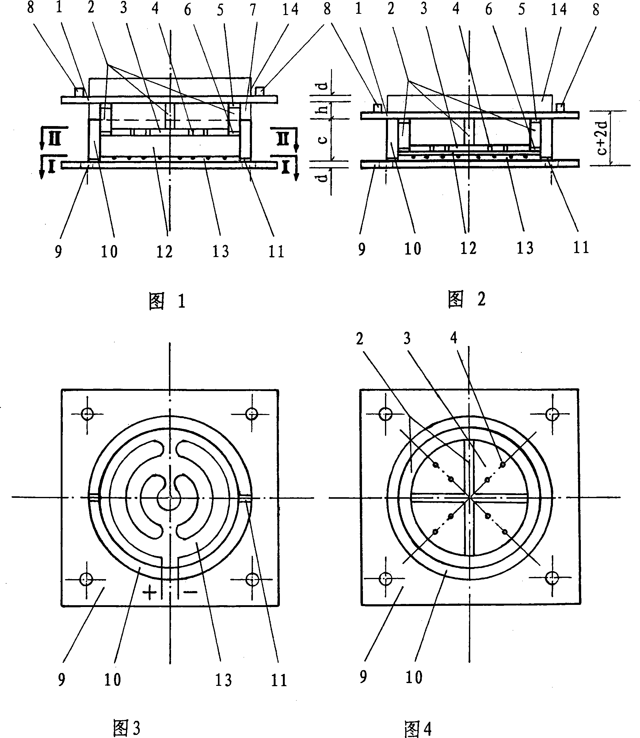
[0025] Accompanying drawing is a kind of specific embodiment of the present invention.

[0026] Bridge settlement support of the present invention comprises finished support 14 and is positioned at the bottom of finished support 14 and is positioned at the bottom of finished support and replaces the lower settlement compression device of bearing pad stone, and this device comprises upper settlement body and lower bottom basin; Upper settlement body consists of roof 1, inner The support plate 2 and the middle bearing plate 3 are composed of the top plate in the horizontal direction. Two side limit blocks 8 are arranged on the left and right sides above the top plate to position and protect the finished bearing. The middle bearing plate is fixed under the top plate through the inner support plate and The top plates are parallel, and there are four cavities between the two parallel plates. The middle support plate is circular and has 8 rheological channels 4. The inner support pla...


PUM


Abstract

The invention relates to a bridge settlement support, which comprises a product support, further comprises an upper settlement compression device which is located on the bottom portion of the product support, the device comprises an upper settlement body and a lower bottom basin, the upper settlement body comprises a top plate, an inner support plate and a middle carrier plate, the top plate is located at the lever direction, the middle carrier plate is fixed on the lower portion of the top plate and is parallel to the top plate through the inner support plate, the middle carrier plate is equipped with a plurality of rheological channels, the inner support plate comprises a ring plate and a baffle which is fixed in the ring plate to form a plurality of cavities, and the upper portion of the ring plate is equipped with a plurality of vent holes. The lower bottom basin comprises a bottom plate and an outer support plate which is fixed on the upper portion of the bottom plate, an overflow orifice is arranged between the bottom plate and the outer support plate, the outer support plate is a ring cylinder which is tightly sleeved on the outer side of the inner support plate, an electric heating disk is laid on the bottom plate, and a compression body is filled between the electric heating disk and the middle carrier plate. The bridge settlement support has the beneficial effects that the disease of bumping at bridge-head is effectively eliminated through that the self settlement drives the floor elevation reduce.

Description

(1) Technical field [0001] The invention relates to a settlement (compression) device, in particular to a bridge settlement support which can drive the elevation of the bridge deck to decrease through its own settlement and effectively eliminate the disease of "jumping at the bridge head". (2) Background technology [0002] At present, regardless of the type of structure, the bridge bearing has only the following three functions: one is to bear the vertical load; the other is to adapt to the rotation of the beam body; the third is to meet the horizontal displacement of the superstructure. The supporting pad stone of the bearing is a reinforced concrete cast-in-place component, which only has the function of limiting and compressing. Therefore, the existing bridge bearings and supporting pads do not have the function of self-settling (compression), and cannot meet the requirements of reducing and adjusting the bridge deck elevation through the settlement of bridge bearings an...

Claims


Application Information

Patent Timeline
Patent Type & Authority Applications(China)
IPC IPC(8): E01D19/04
Inventor 郝贤成牛树河郝镭
Owner 郝贤成
Why Eureka
Try Eureka