Non-reignition disconnector

A circuit breaker and reflashing technology, which is applied to high-voltage air circuit breakers, circuits, electrical components, etc., can solve problems such as temporary solutions but not root causes

Inactive Publication Date: 2014-02-12
XI AN MENGCHUANG ELECTRICAL APPLIANCE
View PDF9 Cites 4 Cited by
  • Summary
  • Abstract
  • Description
  • Claims
  • Application Information

AI Technical Summary

Problems solved by technology

At present, there is no better way to solve this problem at home and abroad, but only to take some backu

Method used


Image

  • Non-reignition disconnector

Examples


Embodiment Construction

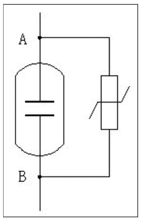
[0021] The invention patent proposes a non-refiring circuit breaker. The fundamental idea to solve this problem is that the reverse voltage appears on the fracture, and before the recovery voltage exceeds the withstand voltage level of the fracture, the voltage difference between the two ends of the fracture must be leveled. In other words, before re-ignition occurs, a leakage bypass is connected in parallel to the fracture to lower the voltage difference and destroy its re-ignition conditions, so that re-ignition can be prevented with half the effort. This requires the completion of the following process in a very short time when the fracture is disconnected: the contacts of the circuit breaker start to separate→detect the voltage between the two contacts→trigger and start the bypass device→the bypass device acts to bypass the fracture→ The bypass circuit discharges and reduces the recovery voltage of the fracture to below the withstand voltage level → the circuit breaker comp...


PUM


Abstract

The invention provides a non-reignition disconnector which comprises a disconnector arc extinguishing chamber, and further comprises a non-linear pressure-sensitive unit, and the non-linear pressure-sensitive unit is connected with an upper electrified portion and a lower electrified portion of a fracture of the disconnector arc extinguishing chamber in parallel. According to the non-reignition disconnector, the voltage difference between the two ends of the facture is leveled before backward voltage and recovery voltage of the fracture exceed a fracture withstand voltage level, and reignition is eliminated.

Description

technical field [0001] The patent of the present invention relates to the field of electrical equipment, in particular to a non-reignition circuit breaker. Background technique [0002] In the power grid at all levels of voltage, all transmission circuits such as overhead lines and cables, and all electrical equipment components such as generators, transformers, motors, reactors, and capacitors are controlled by circuit breakers (commonly known as switches). These circuit breakers are composed of fracture, arc extinguishing chamber and operating mechanism, which are used to manually or automatically open and close the normal working current and short-circuit current. When the two contacts of the fracture are disconnected, the arc will be drawn, and the arc will be extinguished in the closed arc extinguishing chamber to complete the disconnection process. The insulation and arc extinguishing media in the arc extinguishing chamber include pressurized or vacuumed air, oil, sul...

Claims


Application Information

Patent Timeline
IPC IPC(8): H01H33/16
Inventor 弋东方弋戈袁国浩
Owner XI AN MENGCHUANG ELECTRICAL APPLIANCE
Why Eureka
Try Eureka