Dominant power system instability mode recognition method based on real-time measurement response information

A power system and pattern recognition technology, applied in the direction of electrical digital data processing, special data processing applications, instruments, etc., can solve problems such as difficult to distinguish instability modes

Active Publication Date: 2014-03-12
STATE GRID CORP OF CHINA +1
View PDF4 Cites 15 Cited by
  • Summary
  • Abstract
  • Description
  • Claims
  • Application Information

AI Technical Summary

Problems solved by technology

The problem of transient power angle stability and transient voltage stability are often intertwined, and it is not easy to distinguish the instability mode of the system after a fault only from the

Method used


Image

  • Dominant power system instability mode recognition method based on real-time measurement response information
  • Dominant power system instability mode recognition method based on real-time measurement response information
  • Dominant power system instability mode recognition method based on real-time measurement response information

Examples


Embodiment 1

[0054] Embodiment 1 provided by the present invention is an embodiment of a dominant identification method for transient power angle instability and transient voltage instability based on real-time measurement information provided by the present invention.

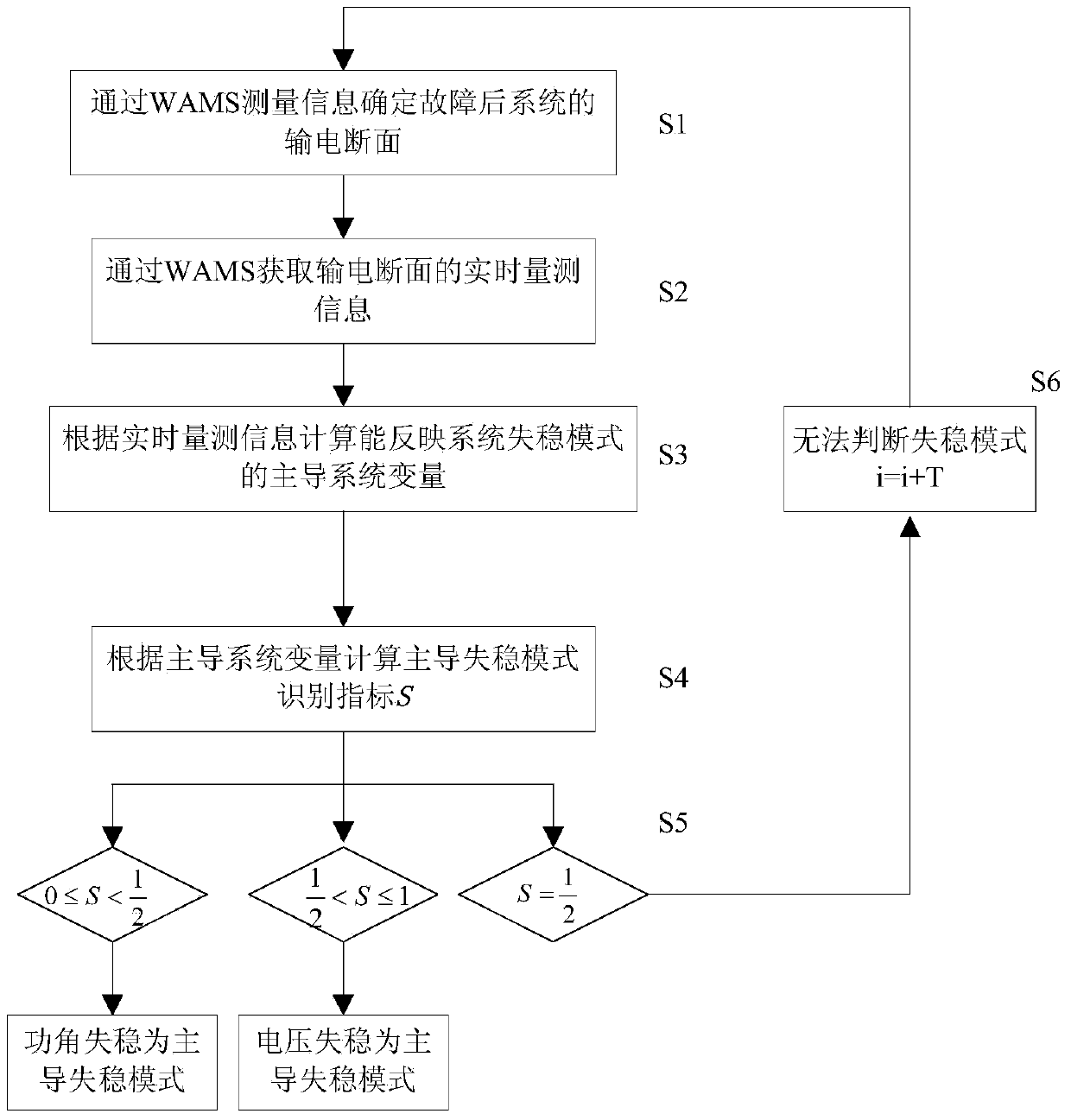
[0055] Specifically, in this embodiment, the dominant instability mode of the multi-machine interconnected power system is judged in real time, and the measurement is carried out through the WAMS system after the fault.

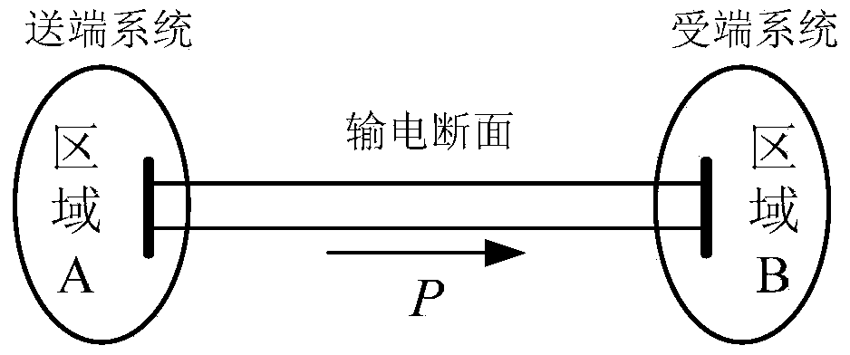
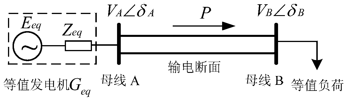
[0056] In step S1, the transmission section of the multi-machine interconnected power system after the fault is determined through the measurement information measured by the WAMS system, and the tie line on the transmission section is identified, so that the multi-machine interconnected power system is divided into two regional systems at the sending and receiving ends.

[0057] In step S2, the dynamic feature information of the transmission section that can reflect the dynamic characteristics of the mult...

Embodiment 2

[0134] Embodiment 2 of a dominant identification method for transient power angle instability and transient voltage instability based on real-time measurement information provided by the present invention is based on the IEEE9 node system, such as Figure 4 As shown, the calculation tool adopted is PSD-FDS (dynamic simulation program for the whole process of power system), and the disturbance response data obtained by the simulation program is used to simulate the real-time measurement data of the wide-area measurement system. Each load in the system is constant impedance. At 0s, a three-phase short circuit occurs on the line bus5-bus7, and the fault is removed at 0.21s, and the connection line Bus9-Bus6 is monitored.

[0135] Step S1': Use the disturbance response data obtained by the simulation program to simulate the real-time measurement data of the wide-area measurement system, and determine the connection line on the transmission section, which is the connection line Bus...


PUM


Abstract

The invention provides a dominant power system instability mode recognition method based on real-time measurement response information. According to the method, a dominant instability mode of a system is judged when a power angle instability phenomenon and a voltage instability phenomenon occur at the same time, and a decision basis is provided for subsequent transient stability emergency control. The method includes the steps of determining a power transmission cross section of the multi-machine interconnected electric power system, obtaining real-time measurement information of the power transmission cross section, calculating dominant system variables which can reflect a system instability mode according to the real-time measurement information, calculating the dominant instability mode identification index according to the dominant system variables, and determining the dominant instability mode of the system according to the dominant instability mode identification index. The method is totally based on the real-time measurement information, dynamic properties of the system are considered fully, and the dominant instability mode of the system when the power angle instability phenomenon and the voltage instability phenomenon occur at the same time can be recognized accurately.

Description

technical field [0001] The invention relates to the field of power systems, in particular to a method for identifying a dominant instability pattern of a power system based on measured response information. Background technique [0002] Transient power angle instability and transient voltage instability are two manifestations of the system in the transient process after a fault. When the system is unstable, the power angle instability may cause voltage collapse, and the voltage collapse may also cause power angle instability. The problem of transient power angle stability and transient voltage stability are often intertwined, and it is not easy to distinguish the instability mode of the system after a fault only from the expression of power angle and voltage. However, system instability must be dominated by one instability mode, and different instability modes may appear successively due to changes in system conditions. There are essential differences between power angle i...

Claims


Application Information

Patent Timeline
IPC IPC(8): G06F19/00
Inventor 汤涌吴为孙华东何剑林伟芳
Owner STATE GRID CORP OF CHINA
Why Eureka
Try Eureka