Supercharge Your Innovation With Domain-Expert AI Agents!

Structure of hydraulic machine material ejection mechanism

A jacking mechanism and hydraulic press technology, applied in the field of hydraulic presses, can solve problems such as increased stroke resistance, easy breakage, and easy wear, and achieve the effects of increased stroke resistance, easy breakage, and easy wear

Inactive Publication Date: 2014-03-19
SUZHOU BLUE KING MACHINE TOOL TECH CO LTD
View PDF1 Cites 4 Cited by
  • Summary
  • Abstract
  • Description
  • Claims
  • Application Information

AI Technical Summary

Problems solved by technology

[0002] The jacking mechanism of a hydraulic press generally includes a hydraulic pad and a push rod. The hydraulic pad is set in the space between the worktable and the base of the hydraulic press. hole, each of the through holes is provided with a same ejector rod, in the existing structure of this type of hydraulic press ejector mechanism, the bottom of the ejector rod is in free contact with the movable cylinder of the hydraulic cushion, because the ejector rod is in the During the ejection process, the force it receives cannot be completely consistent with the axis of the ejector rod, so the ejector rod is prone to instability, resulting in increased stroke resistance, not only easy to wear, but also easy to break, and thus Cause equipment failure and product quality accidents, the technical scheme disclosed in Chinese Patent No. 201120125368.2 titled Hydraulic Press Stretch Forming Jacking Hydraulic Cushion, attempts to solve the above-mentioned problems, but the technical scheme only sets some close to each other at the bottom of the ejector rods. Since the bottom of the ejector rod is still in a free state, the bottom may deviate from the axis position under the force component, which will still increase the stroke resistance, which is not only easy to wear, but also easy to break , and thus lead to equipment failure and product quality accidents

Method used


Image

  • Structure of hydraulic machine material ejection mechanism
  • Structure of hydraulic machine material ejection mechanism

Examples


specific Embodiment approach

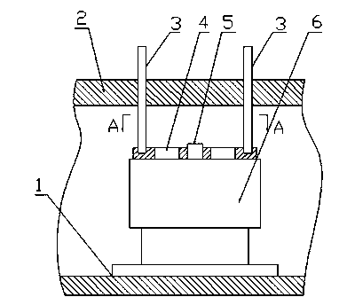
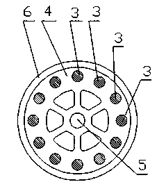
[0009] combined with figure 1 , figure 2 , the specific embodiment of the present invention is:

[0010] The structure of a hydraulic machine jacking mechanism according to the present invention is composed of: machine base (1), machine table (2), ejector rod (3), positioning disc (4), positioning shaft (5), hydraulic The pad (6) is composed of a hydraulic pad (6), which is characterized in that a hydraulic pad (6) is fixed in the space between the machine base (1) and the machine table (2), and the center of the hydraulic pad (6) is fixed A positioning shaft (5), a positioning disc (4) is arranged on the upper surface of the movable cylinder of the hydraulic pad (6), the positioning shaft (5) passes through the middle hole of the positioning disc (4) and is combined with the positioning disc (4), The upper plane of the positioning disc (4) is formed with blind holes in the circumference division, and the machine tool table (2) directly above the blind holes is formed...


PUM


Abstract

The invention provides a structure of a hydraulic machine material ejection mechanism and belongs to the technical field of hydraulic machines. The structure of the hydraulic machine material ejection mechanism is characterized in that a hydraulic cushion is arranged and fixed to the space between a machine tool base and a machine tool workbench, a locating shaft is arranged and fixed to the center of the hydraulic cushion, a locating disc is fixed to the upper plane of a movable cylinder of the hydraulic cushion through a locating shaft, blind holes distributed in the circumferential direction are formed in the upper plane of the locating disc, corresponding through holes are formed in the machine tool workbench located over the blind holes, an ejector rod is arranged in each through hole, and the bottom of each ejector rod is arranged in the corresponding blind hole in the locating disc under the ejector rod. The structure of the hydraulic machine material ejection mechanism has the advantages that the ejector rods are not prone to abrasion and breakage and the shortages of a device fault and a product quality accident which are caused by abrasion and breakage of the ejector rods are overcome.

Description

technical field [0001] The invention relates to a hydraulic press, in particular to the structure of a jacking mechanism of a hydraulic press, and belongs to the technical field of hydraulic presses. Background technique [0002] The jacking mechanism of a hydraulic press generally includes a hydraulic pad and a push rod. The hydraulic pad is set in the space between the worktable and the base of the hydraulic press. hole, each of the through holes is provided with a same ejector rod, in the existing structure of this type of hydraulic press ejector mechanism, the bottom of the ejector rod is in free contact with the movable cylinder of the hydraulic cushion, because the ejector rod is in the During the ejection process, the force it receives cannot be completely consistent with the axis of the ejector rod, so the ejector rod is prone to instability, resulting in increased stroke resistance, not only easy to wear, but also easy to break, and thus Cause equipment failu...

Claims


Application Information

Patent Timeline
IPC IPC(8): B30B15/00
Inventor 孙生强
Owner SUZHOU BLUE KING MACHINE TOOL TECH CO LTD
Features
  • R&D
  • Intellectual Property
  • Life Sciences
  • Materials
  • Tech Scout
  • Unparalleled Data Quality
  • Higher Quality Content
  • 60% Fewer Hallucinations
Learn More