Magnetic lock catch

A technology of magnetic lock and locking section, applied in the direction of connecting components, bolts, mechanical equipment, etc., can solve the problems of low connection efficiency and difficult positioning, and achieve the effect of high connection efficiency and fast connection

Inactive Publication Date: 2014-03-26
苏州方桥机电有限公司
View PDF11 Cites 8 Cited by
  • Summary
  • Abstract
  • Description
  • Claims
  • Application Information

AI Technical Summary

Problems solved by technology

Among them, the detachable connection mainly includes connection methods such as threads, pins, and chains. In the field of mechanical design and manufacturing, if a large number of parts need to be connected together at the same time, the traditional detachable connection method has difficulty in positioning and low connection efficiency. question

Method used


Image

  • Magnetic lock catch
  • Magnetic lock catch
  • Magnetic lock catch

Examples


Embodiment Construction

[0019] The following descriptions are only preferred embodiments embodying the principles of the present invention, and do not therefore limit the protection scope of the present invention.

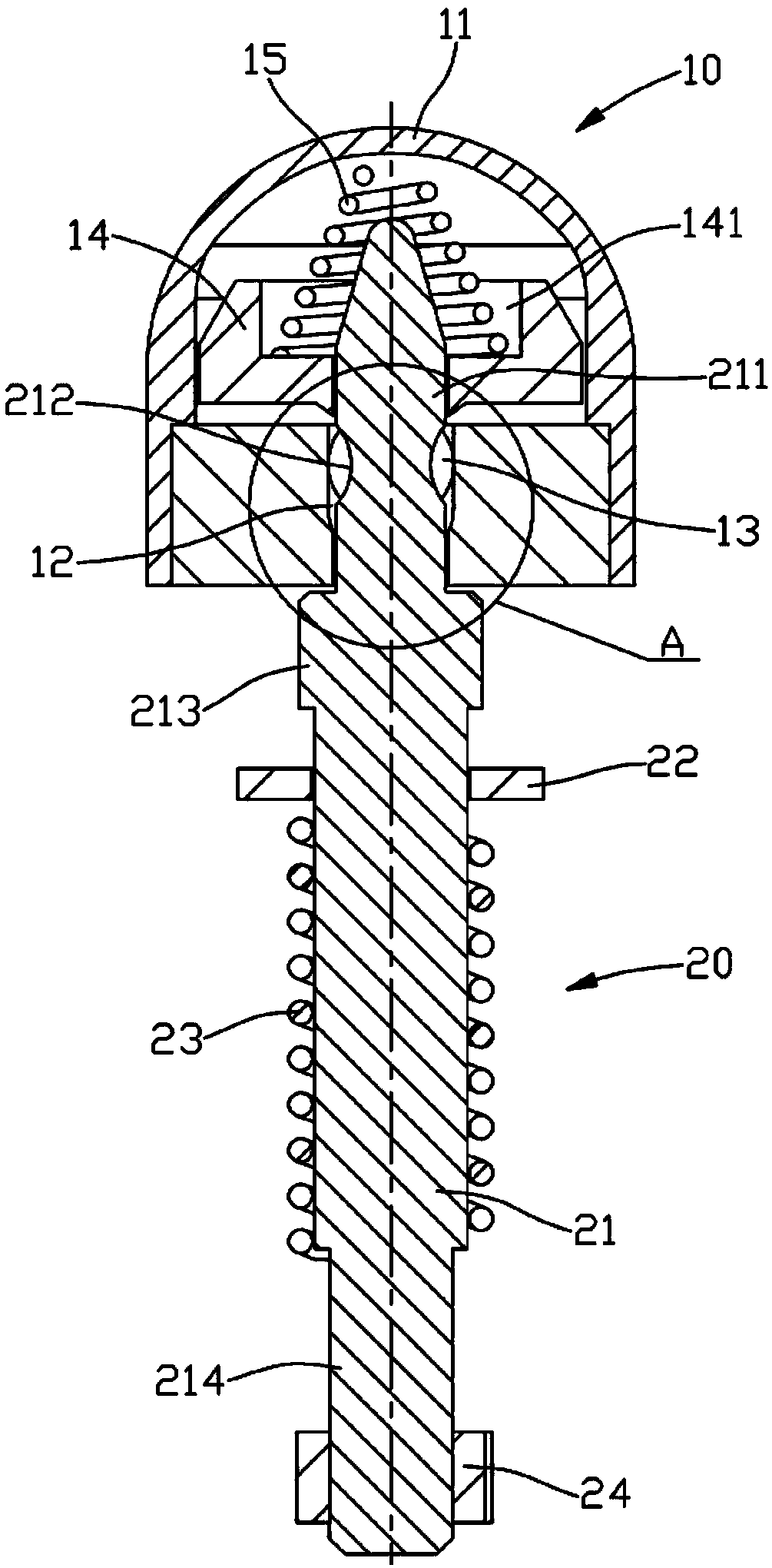
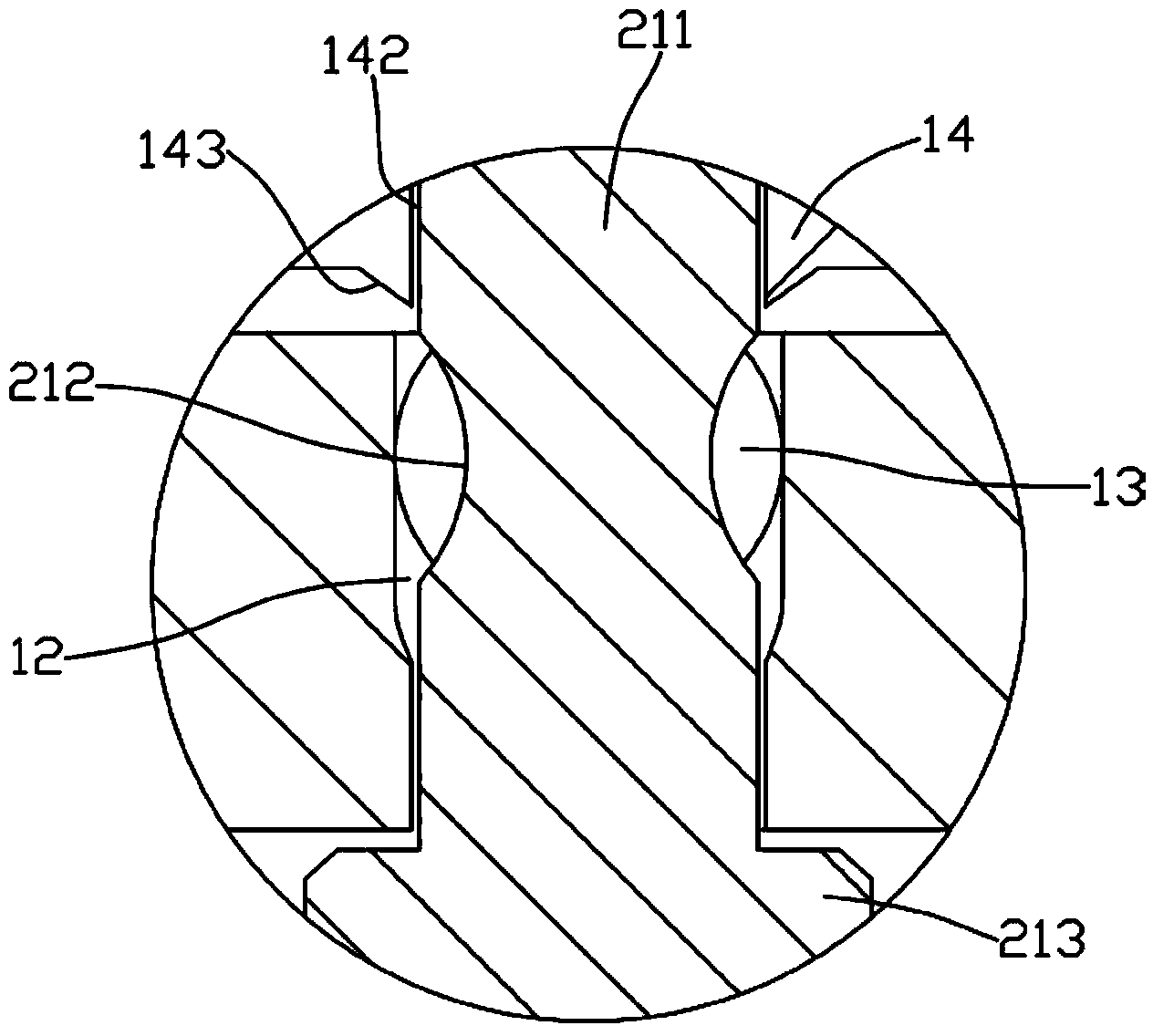
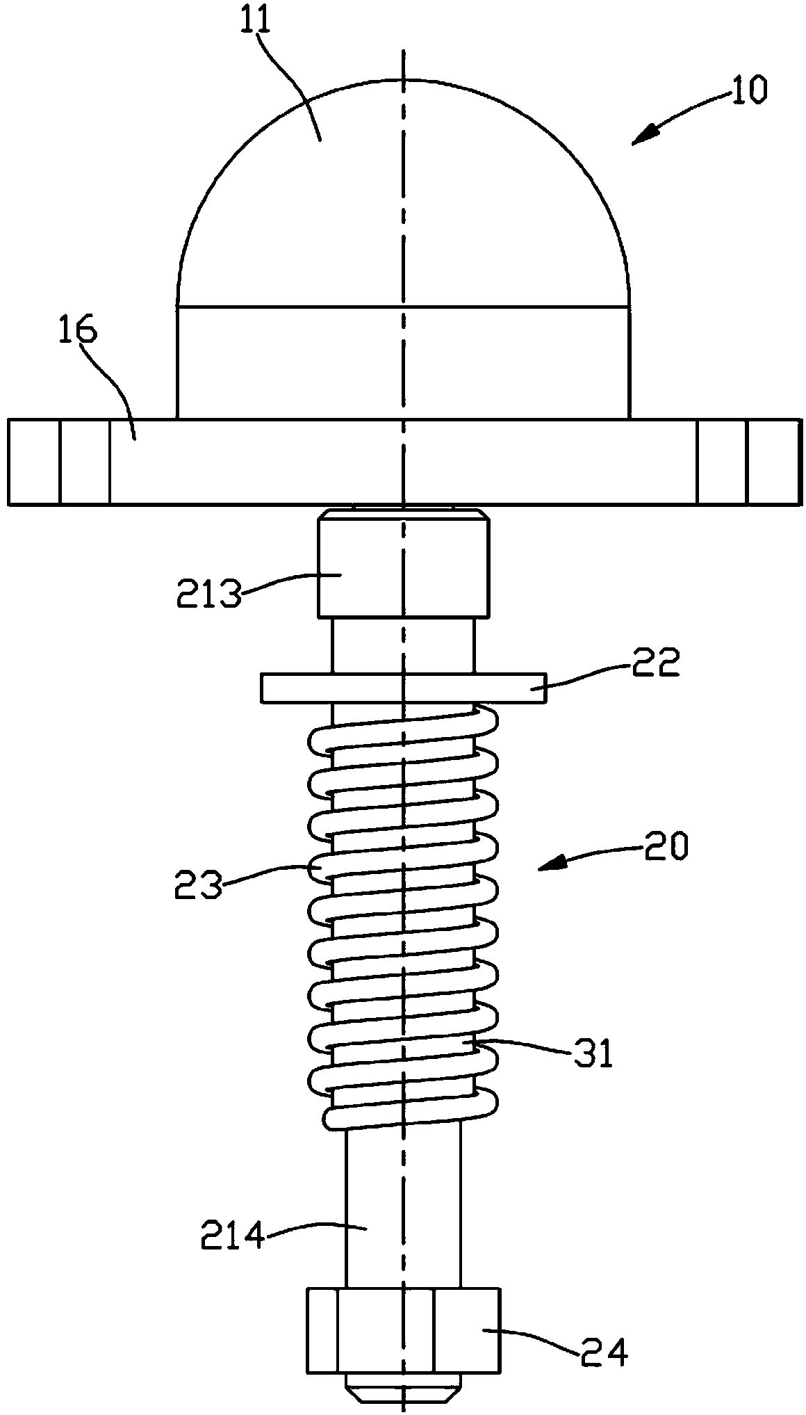
[0020] See Figure 1 to Figure 3 As shown: the magnetic lock of the present invention is composed of a locking device 10 and a positioning device 20, wherein:

[0021] The locking device 10 has a casing 11, the bottom of the casing 11 has a steel ball chute 12 with a large upper part and a smaller one at the lower part. The steel ball pressing block 14 and the locking spring 15 matched with the magnetic block; the steel ball pressing block 14 can slide in the casing 11, and a spring positioning groove 141 and a positioning pin guide hole 142 are opened in the middle, and the bottom of the steel ball pressing block 14 corresponds to the steel ball chute 12 A tapered protrusion 143 is formed at the position. The locking spring 15 is a conical spring, its upper end is against the inner top...


PUM


Abstract

The invention discloses a magnetic lock catch which is composed of a locking device and a positioning device. The locking device is provided with an outer shell, a big end up steel ball sliding groove is formed in the bottom of the outer shell, a steel ball is arranged in the steel ball sliding groove, a steel ball pressing block and a locking spring which are matched with a magnetic block are arranged at the upper end of the steel ball sliding groove in the outer shell, and the locking spring presses the steel ball in the steel ball sliding groove through the steel ball pressing block. The positioning device comprises a positioning pin, a movable gasket, a positioning spring and a fixing piece. The front end of the positioning pin is a locking section which can penetrate through the steel ball sliding groove, an arc-shaped groove matched with the steel ball is formed in the middle portion of the locking section, the movable gasket and the positioning spring are arranged on the positioning pin in a sleeved mode, and the fixing piece is connected with the rear end of the positioning pin. The magnetic lock catch can achieve movable connection between two independent parts, is suitable for enabling a plurality of parts to be movably connected with other parts simultaneously, and has the advantages of being precise in positioning and high in connecting efficiency.

Description

Technical field: [0001] The invention relates to the technical field of mechanical connection, in particular to a magnetic lock that can movably connect two parts together. Background technique: [0002] Mechanical connection can connect two or more independent parts together, and can be divided into detachable connection and non-detachable connection according to different connection methods. Among them, the detachable connection mainly includes connection methods such as threads, pins, and chains. In the field of mechanical design and manufacturing, if a large number of parts need to be connected together at the same time, the traditional detachable connection method has difficulty in positioning and low connection efficiency. question. Invention content: [0003] The purpose of the present invention is to address the shortcomings of the prior art and provide a magnetic lock that can not only realize the flexible connection between two independent parts, but also be app...

Claims


Application Information

Patent Timeline
Patent Type & Authority Applications(China)
IPC IPC(8): F16B19/02F16B21/12
Inventor 史伯军
Owner 苏州方桥机电有限公司
Why Eureka
Try Eureka