Pin puller

A pin puller and shell technology, applied in the field of pin pullers, can solve problems such as difficulty in pulling out

Inactive Publication Date: 2015-04-29
AMPHENOL CHANGZHOU ELECTRONICS
View PDF0 Cites 6 Cited by
  • Summary
  • Abstract
  • Description
  • Claims
  • Application Information

AI Technical Summary

Problems solved by technology

However, during equipment maintenance, we often encounter locating pins with internal threads, and locating pins usually sink into the pin holes of the equipment, making it difficult to pull out

Method used


Image

  • Pin puller

Examples


Embodiment Construction

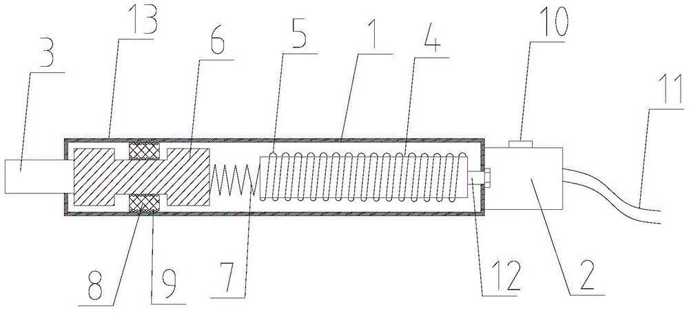
[0011] As shown in the figure, the pin puller includes a shell 1, a handle 2 and a replaceable screw head hole 3, the handle 2 is set at the rear end of the shell 1, the replaceable screw head hole 3 is set at the outer end of the shell 1, and the screw head hole can be replaced 3 pass through the front end of the shell 1, the shell 1 rear portion is provided with a soft magnet 4, the soft magnet 4 is spirally provided with a wire 5, the front end of the soft magnet 4 front end shell is provided with a magnetizer 6, and a magnetizer 6 is arranged between the magnetometer 6 and the soft magnet 4. There is a spring 7, one end of the spring 7 is connected with the magnetizer 6, one end is connected with the soft magnet 4, the front end of the magnetizer 4 is connected with the replaceable screw head hole 3, and the upper and lower ends of the magnetizer 6 are provided with long concave grooves, and the magnetizer 6 and the A slider 8 is provided between the inner walls of the hous...


PUM


Abstract

The invention relates to the field of hardware tools, in particular to a pin puller, which comprises a shell, a handle and a replaceable screwhead hole. The pin puller is characterized in that a soft magnet is arranged on the rear part of the shell, a wire is helically wound on the soft magnet, a magnetizer is arranged at the front end, at the front end in the shell, of the soft magnet, a spring is arranged between the magnetizer and the soft magnet, one end of the spring is connected with the magnetizer, the other end of the spring is connected with the soft magnet, the front end of the magnetizer is connected with the replaceable screwhead hole, the upper end and lower end of the magnetizer are provided with long notches, a slider is arranged between the magnetizer and the shell, the cross-sectional area of the slider is less than the cross-sectional area of the long notches, balls are arranged at the upper end surface and lower end surface of the slider, and the balls are in contact with the bottoms of the long notches and the inner wall of the shell. The pin puller provided by the invention is convenient and easy to use, and has a long service life.

Description

technical field [0001] The invention relates to the field of hardware tools, in particular to a pin puller. Background technique [0002] Locating pins mainly play the role of positioning and connection in equipment. Locating pins are the most widely used in molds. Often the precision of these molds is particularly high, and if the template is fixed only by bolts, the accuracy cannot be achieved. Use the positioning pin to achieve the purpose of positioning, or to prevent problems such as wrong installation position and direction. However, during equipment maintenance, positioning pins with internal threads are often encountered, and the positioning pins usually sink into the pin holes of the equipment, making it difficult to pull out. Contents of the invention [0003] In view of the above problems, the present invention provides a pin puller that is easy to use, labor-saving, and has a long service life. Realize the technical scheme of the present invention [0004] T...

Claims


Application Information

Patent Timeline
Patent Type & Authority Applications(China)
IPC IPC(8): B25B27/02
CPCB25B27/02
Inventor 陆尧谭礼旗王世艮王焕刚
Owner AMPHENOL CHANGZHOU ELECTRONICS
Why Eureka
Try Eureka