Multi-way valve and hydraulic control system

A multi-way valve and total control technology, applied in the direction of fluid pressure actuators, servo motors, servo motor components, etc., can solve problems such as complex pipelines, and achieve the effect of simple connection pipelines

Active Publication Date: 2014-04-30
XCMG CONSTR MACHINERY
View PDF6 Cites 8 Cited by
  • Summary
  • Abstract
  • Description
  • Claims
  • Application Information

AI Technical Summary

Problems solved by technology

Its advantage is that each action limit is independent of each other. The disadvantage is that in order to realize the control of the pump, a complex shuttle valve group valve block needs to be connected in series on the pilot oil circuit to screen out the maximum pilot control pressure, and the pipeline is more complicated.

Method used


Image

  • Multi-way valve and hydraulic control system
  • Multi-way valve and hydraulic control system
  • Multi-way valve and hydraulic control system

Examples


Embodiment Construction

[0031] The technical solutions of the present invention will be described in further detail below with reference to the accompanying drawings and embodiments.

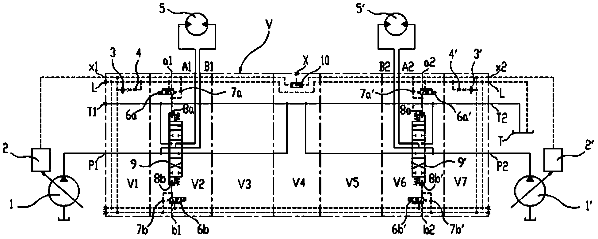
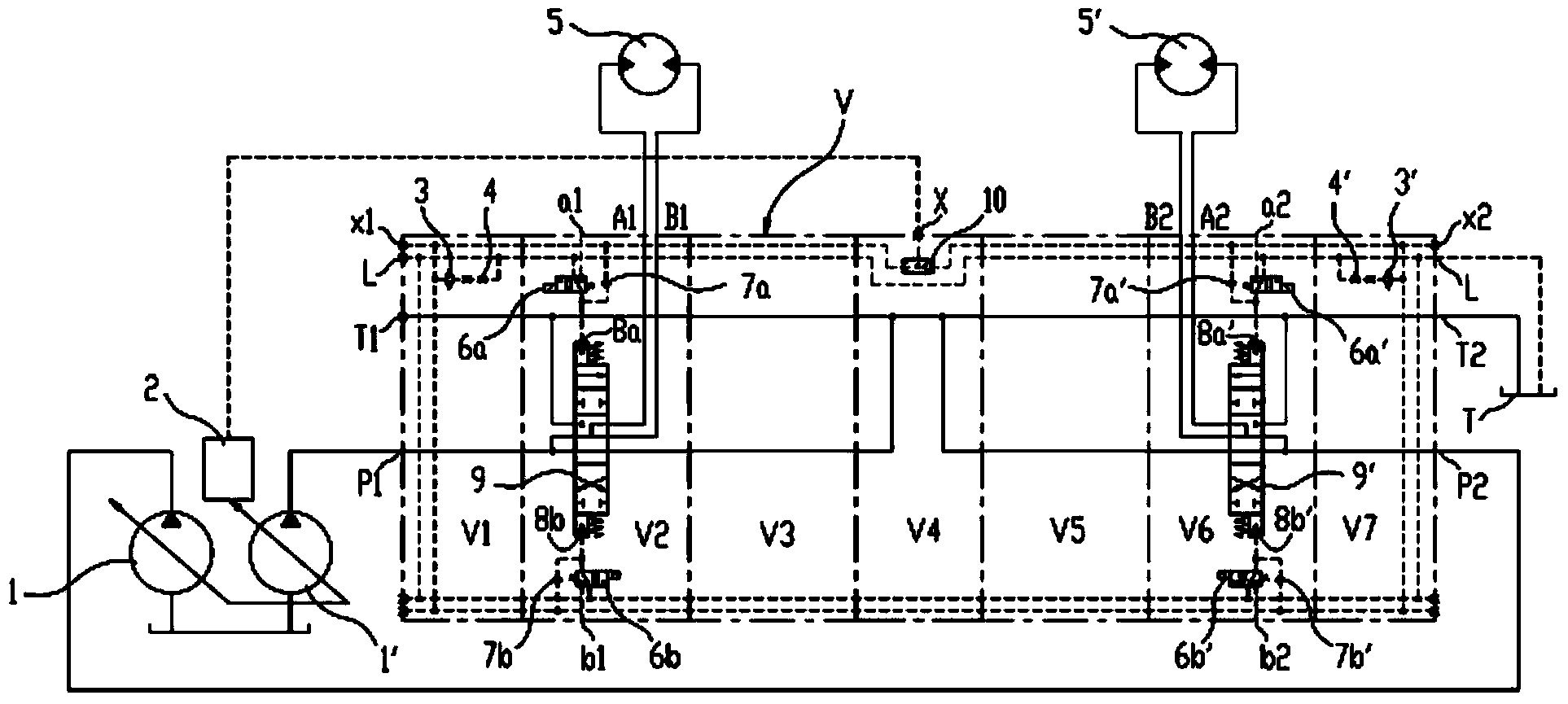
[0032] The present invention provides a kind of multi-way valve, adopts such as figure 2 and image 3 A combination of multiple worksheets shown in . exist figure 2 and image 3 Among them, the multi-way valve V is composed of working couplets V1-V7, among which the working couplets V1 and V7 are used to connect the main pumps 1 and 1', so it can be called the oil inlet joint, and the working couplet V4 is between the two working couplets V2-V7. Between V3 and V5-V6, it can be called the middle joint. Among them, the main reversing valve and the corresponding pilot oil circuit switch control structure are respectively set in the working links V2-V3 and V5-V6. figure 2 and image 3 The hydraulic principle structures of the corresponding main reversing valves 9 and 9' are described by taking working links V2 and...


PUM


Abstract

The invention relates to a multi-way valve and a hydraulic control system. A combined type of a plurality of working groups is adopted in the multi-way valve. Main reversing valves and corresponding pilot oil path on-off control structures are arranged in part of the working groups. The pilot oil path on-off control structures are used for controlling pilot pressure oil between pilot control oil ports and pilot control cavities of the main reversing valves to be supplied or interrupted so that working or unloading of the working groups corresponding to the main reversing valves can be achieved. Compared with an existing hydraulic control system, the hydraulic control system cam limit independent motion and is not provided with special manifold blocks for the main reversing valves of the working groups to control the pilot pressure oil, and therefore the hydraulic control system is simpler in structure and connecting pipeline.

Description

technical field [0001] The invention relates to the field of engineering machinery, in particular to a multi-way valve and a hydraulic control system. Background technique [0002] As a special lifting equipment, the crane usually needs to realize the following actions: lifting hook (hereinafter referred to as: lifting), lifting jib (hereinafter referred to as: luffing), slewing, walking and other operations. Due to the limited height of the boom frame of the crane, if the hook is lifted too high, the boom frame will be damaged, and if the hook is dropped too low, the number of remaining turns of the wire rope on the winch may be too small, which will cause the accident that the wire rope is separated from the winch; The angle of the boom should not be too large, otherwise it may cause the danger of the boom tilting backward, and the angle of the boom should not be too small, so as not to cause the vehicle to be unstable enough to cause a rollover accident. In order to meet...

Claims


Application Information

Patent Timeline
Patent Type & Authority Applications(China)
IPC IPC(8): F15B13/02F15B11/17
Inventor 陈远泽罗康松余钦伟张伟
Owner XCMG CONSTR MACHINERY
Why Eureka
Try Eureka