Transplanter

A technology for transplanting machines and transplants, which is applied in the field of transplanting machines, can solve the problems that the intervals cannot be equal intervals, cannot be configured, and cannot be planted for seedlings, etc., so as to improve the replenishment workability, facilitate the interval between rows of transplanting, and change easily Effect

Active Publication Date: 2014-05-21
ISEKI & CO LTD
View PDF6 Cites 16 Cited by
  • Summary
  • Abstract
  • Description
  • Claims
  • Application Information

AI Technical Summary

Problems solved by technology

[0008] However, in the above-mentioned conventional seedling transplanting machine, all (four) seedling drop supply positions corresponding to each row cannot be arranged in the linear portion, so that the seedlings cannot be transplanted at equal intervals between rows.
[0009] That is, in the above-mentioned existing seedling transplanting machine, it is configured that when the seedling transplanter reaches the top dead center position and the seedling storage body reaches the seedling drop supply position directly above the seedling transplanter, the seedlings are moved from the seedling storage body. The seedlings are dropped and supplied to the seedling transplanter, and the seedling storage bodies are respectively corresponding to each row. Therefore, the intervals between the drop supply positions of the rows on the circular path of the seedling storage bodies cannot be equal.

Method used


Image

  • Transplanter
  • Transplanter
  • Transplanter

Examples


Embodiment Construction

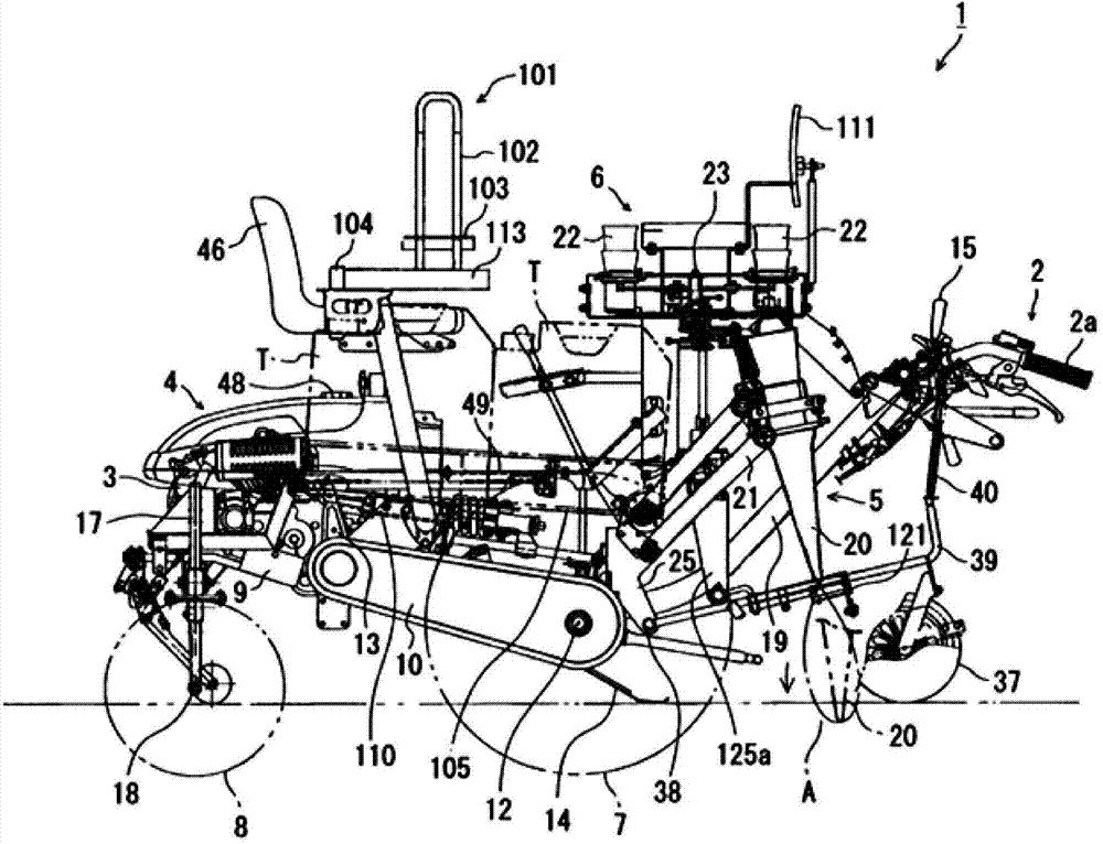
[0053] Hereinafter, embodiments specifically configured based on the above-mentioned technical idea will be described with reference to the drawings. In addition, in the following description, the side on which the joystick 2 is arrange|positioned is made into rear, and the side opposite to it, ie, the side on which the engine 3 is arrange|positioned, is made into front. Also, let the right-hand side when going from the rear side of the body toward the front side of the body be right, and let the left-hand side be left.

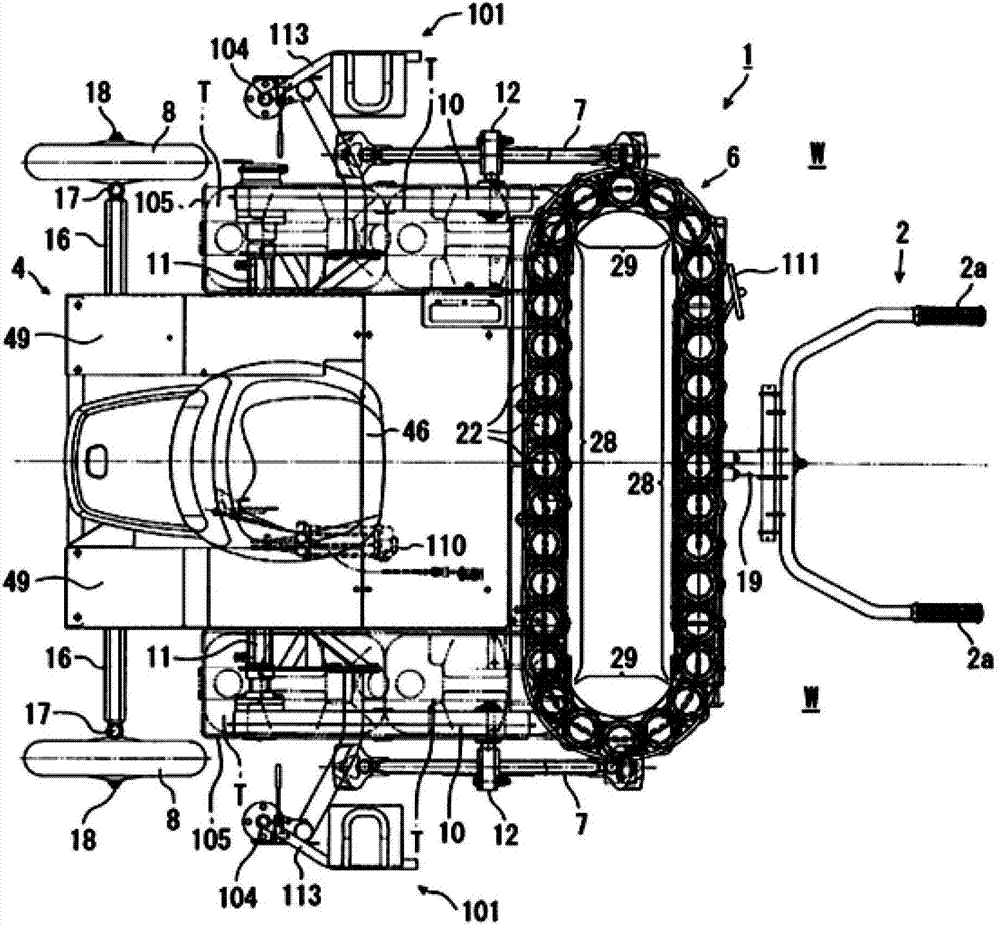
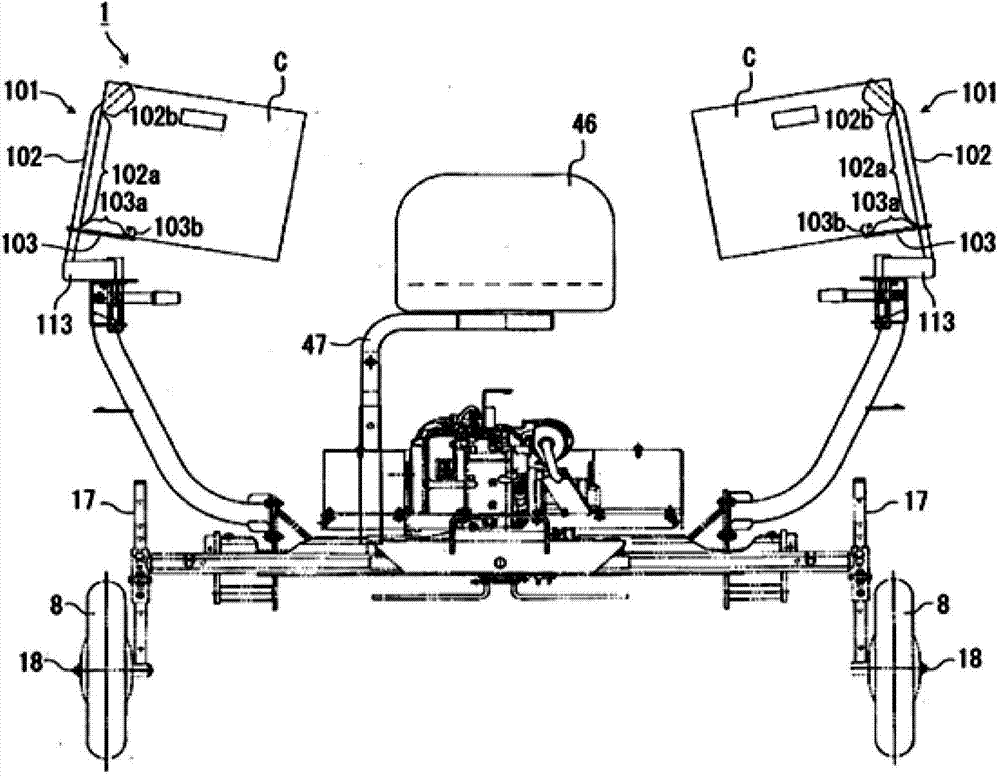
[0054] figure 1 shows a side view of a transplanting machine (seedling transplanting machine) according to the first embodiment of the present invention, figure 2 shown in figure 1 The top view of the seedling transplanting machine, image 3 shown in figure 1 front view of a seedling transplanting machine. exist image 3 Among them, the parts located at the rear of the traveling vehicle body 4 such as the operating handle 2 are omitted.

[0055] This ...


PUM


Abstract

The invention aims to provide a transplanter which transplants more than three lines of transplanted object plant. The transplanter can configure all seedling falling feeding positions at a linear part and separately inserts the seedlings in an expected transplanting line distance. The transplanter is configured in a manner which is characterized in that: upper dead point falling supplying positions (31b,31c), an upper moving falling supplying position (31a) and a lower moving falling supplying position (31d) are configured at a linear part (28) which surrounds a moving path; at the upper dead point falling supplying positions (31b,31c), when a transplanting device arrives at an upper dead point or a position which is next to the upper dead point, the transplanting object plant falls and is supplied to the transplanting device; at the upper moving falling supplying position (31a), at the time when the transplanting device upwards moves to the upper dead point, the transplanting object plant falls and is supplied to the transplanting device; and at the lower moving falling supplying position (31d), at the time when the transplanting device downwards moves through the upper dead point, the transplanting object plant falls and is supplied to the transplanting device.

Description

technical field [0001] The present invention relates to a transplanting machine for transplanting vegetable seedlings such as onions and lettuce, seed potatoes, etc. to fields. Background technique [0002] In the past, there is known a seedling transplanting machine that inserts seedlings supplied from a seedling supply device that moves around a plurality of seedling storage bodies. The seedling supply device of this seedling transplanting machine has a relatively small and lightweight structure. , and this seedling transplanting machine transplants seedlings in more than 3 rows (for example, refer to Patent Document 1). [0003] The seedling transplanting machine described in Patent Document 1 is provided with a plurality of (four) seedling implanters arranged side by side in the left-right direction, and is provided with a seedling supply device for supplying seedlings to these plurality of seedling implanters. The up and down moving mechanism moves up and down accordin...

Claims


Application Information

Patent Timeline
IPC IPC(8): A01C11/02
Inventor 村并昌实大久保嘉彦山根畅宏东幸太田崎昭雄
Owner ISEKI & CO LTD
Why Eureka
Try Eureka