
Potential definition of input lines of inverter

An input line and inverter technology, applied in the direction of irreversible DC power input conversion to AC power output, AC power input conversion to DC power output, photovoltaic power generation, etc. simple limited effect

Inactive Publication Date: 2014-05-21
SMA SOLAR TECH AG
View PDF7 Cites 2 Cited by
  • Summary
  • Abstract
  • Description
  • Claims
  • Application Information

AI Technical Summary

Problems solved by technology

But there is no setting: these capacitors are charged to a DC voltage
The mentioned literature does not at all investigate the definition of the input line potential of the inverter bridge and thus of the connected photovoltaic generator with respect to ground

Method used


Image

  • Potential definition of input lines of inverter
  • Potential definition of input lines of inverter
  • Potential definition of input lines of inverter

Examples


Embodiment Construction

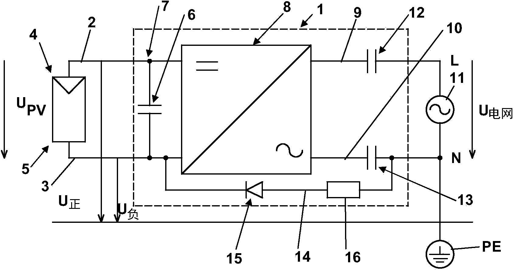
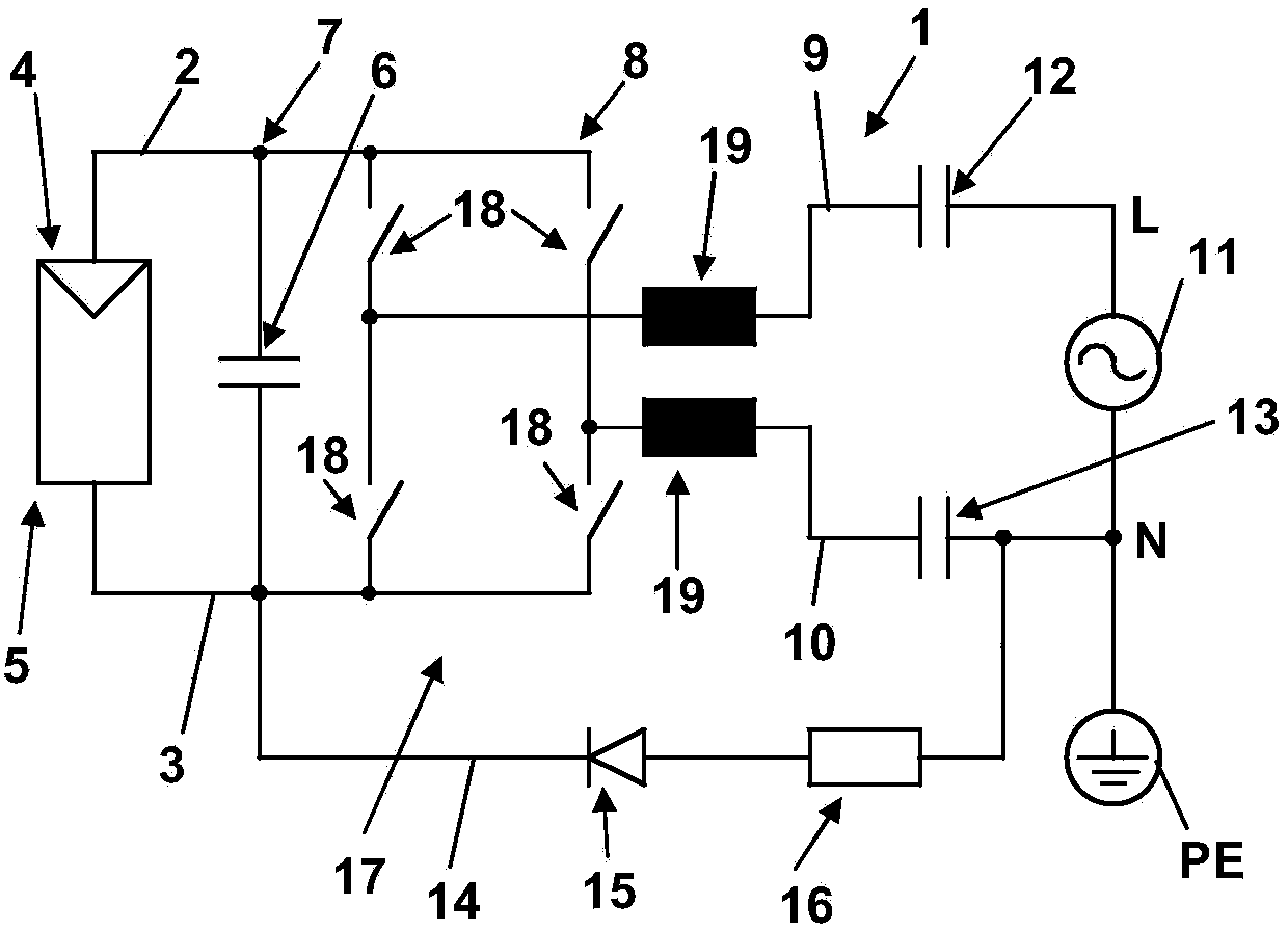
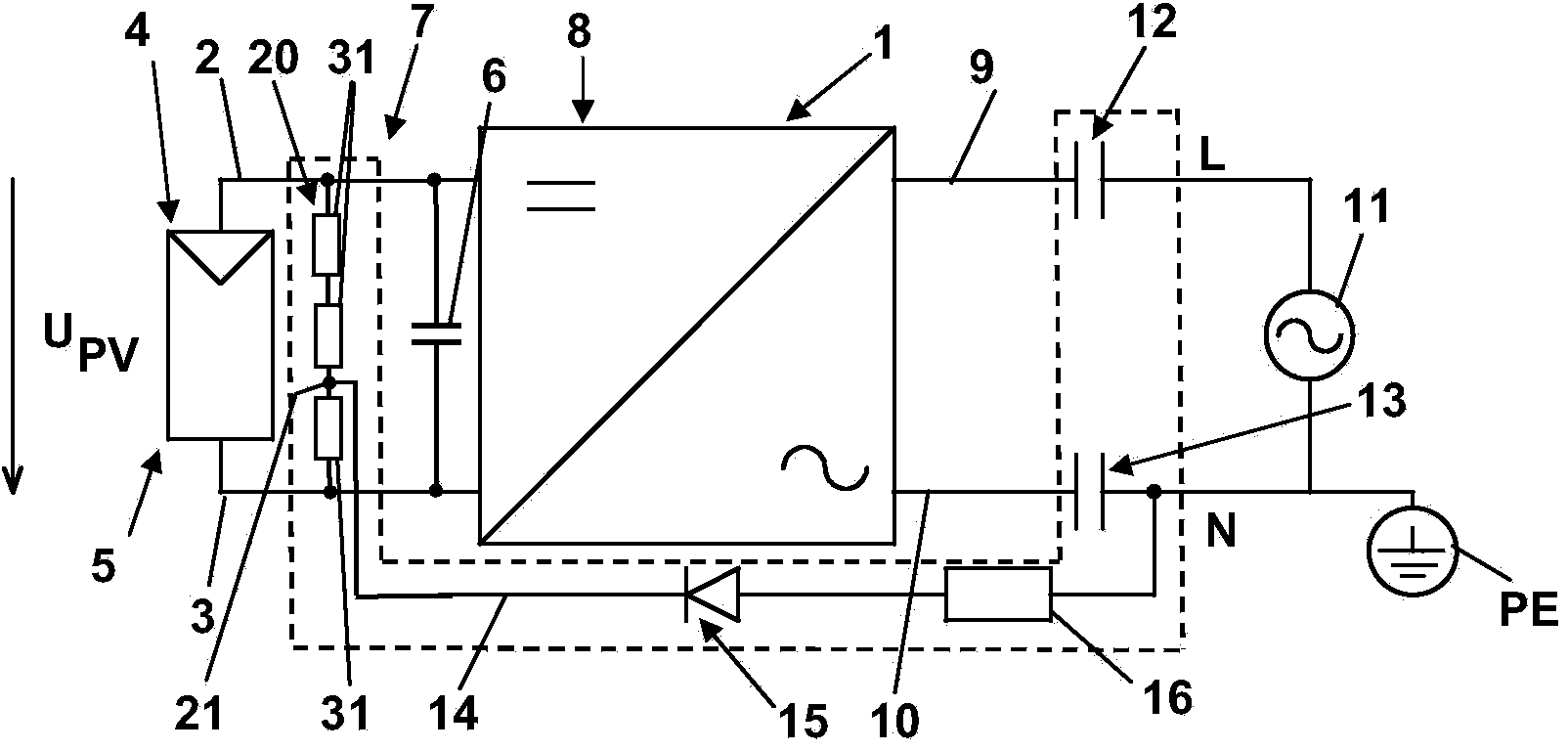
[0039] exist figure 1 The inverter 1 shown in has two input lines 2 and 3 which are connected to a direct current source 4 , here in the form of a photovoltaic generator 5 . The buffer capacitor 6 between the input lines 2 and 3 forms a DC voltage intermediate circuit 7 , which provides the voltage U of the photovoltaic generator 5 between the input lines 2 and 3 . PV Stablize. The snubber capacitor 6 can, as known, also be constructed from a plurality of individual snubber capacitors. After the DC voltage intermediate circuit 7 , the input lines 2 and 3 are connected to a DC / AC converter 8 . The current-carrying output lines 9 and 10 from the DC / AC converter 8 are connected to an alternating current network 11 . Specifically, the output line 9 is connected to the live line of the alternating current grid 11 and the output line 10 is connected to the neutral line N. Between the DC / AC converter 8 and the alternating current network 11, a capacitor 12 or 13 is arranged in th...


PUM


Abstract

In order to define an electric potential of input lines (3) of an inverter (1) relative to ground (PE), capacitors (12, 13) are arranged in all current-carrying output lines (9, 10) of the inverter (1) and charged to a DC voltage in order to shift by said DC voltage the electric potential of the input lines (2, 3) with respect to a reference potential applied to the current-carrying output lines of the inverter.

Description

technical field [0001] The invention relates to a method for limiting the potential of an input line of an inverter with respect to ground and to an inverter having: an input line for connecting a direct current source; an output line for supplying an alternating current ; Means for limiting the input line potential with respect to ground. [0002] In particular, the invention relates to the technical field of feeding electrical power from a photovoltaic generator into an alternating current grid. The alternating current grid can in particular be a public grid, but also an island grid. Depending on the structure of the photovoltaic generator module, it may be advantageous or even required for a long service life to maintain the photovoltaic generator as a whole at a positive or negative potential with respect to ground in order to prevent the modules from Negative or positive voltage in its surroundings. This applies in particular in so-called thin-layer modules. Backgrou...

Claims


Application Information

Patent Timeline
IPC IPC(8): H02M7/48H02J3/38
CPCH02M7/48H02J2300/10H02J2300/24H02J3/381Y02E10/56H02M7/05
Inventor W·福格特
Owner SMA SOLAR TECH AG
Learn More