Wire-pulling iron wire binding machine

A wire puller and binding device technology, which is applied in the field of pull wire binding devices, can solve the problems of loose wire, damage to the galvanized protective layer on the surface of the wire, convex belly or exposed seams, etc.

Inactive Publication Date: 2014-06-18
MEISHAN POWER SUPPLY CO STATE GRID SICHUAN ELECTRIC POWER CO +1
View PDF0 Cites 4 Cited by
  • Summary
  • Abstract
  • Description
  • Claims
  • Application Information

AI Technical Summary

Problems solved by technology

The main disadvantage is: when winding, it takes force to bind tightly, and the technical proficiency is required to be high, otherwise the iron wire after binding is not tight,

Method used


Image

  • Wire-pulling iron wire binding machine
  • Wire-pulling iron wire binding machine
  • Wire-pulling iron wire binding machine

Examples


Embodiment Construction

[0016] The patent will be further described below in conjunction with specific embodiments.

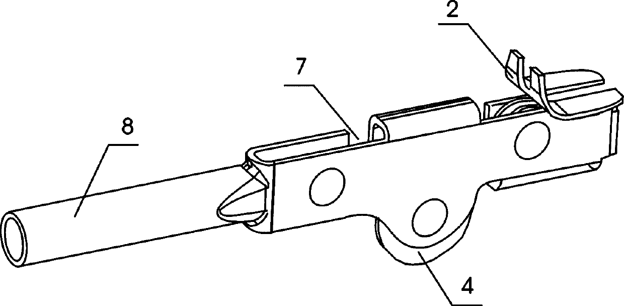
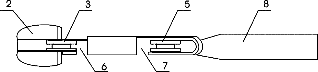
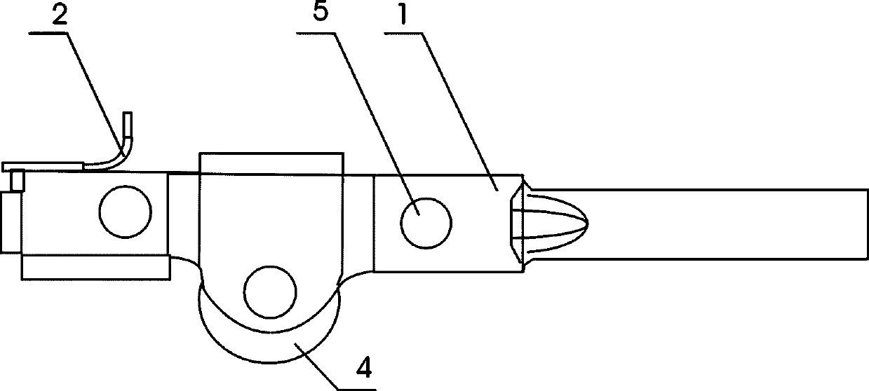
[0017] The pull wire binding device is composed of the main body of the puller, the positioning clip, the front roller, the middle roller, the rear roller, the front groove, the rear groove, and the steel pipe for the handle. The upper part of the front roller is provided with a positioning clip, and a gap is set between the positioning clips. The gap between the positioning clip and the position of the roller groove of the front roller is on the same center line, and the middle roller is set between the front roller and the rear roller. A wire passage is set on the main body of the puller, and a wire passage is set on the main body of the wire puller between the middle roller and the rear roller, and the steel pipe of the handle is welded at the end of the main body of the puller. After completion, pour the edge to 0.5 degrees to ensure that it does not scratch your hands. The diame...


PUM


Abstract

The invention relates to an electric pole wire pulling tool, in particular relates to a wire-pulling iron wire binding machine. A wire puller body is provided with a front idler wheel, a middle idler wheel and a rear idler wheel through rivets, wherein the upper part of the front idler wheel is provided with positioning clips; a gap is reserved in the positioning clips; the gap of the positioning clips is in the same center line with the position of the idler wheel groove of the front idler wheel; the middle idler wheel is arranged between the front and rear idler wheels; a wire passage is arranged on the wire puller body between the middle and rear idler wheels; a handheld steel pipe is welded with the tail end of the wire puller body. According to the wire-pulling iron wire binding machine, high expert skill is not needed, the bound iron wire is tight and order, and meanwhile, the galvanized protection layer on the surface of the iron wire is protected.

Description

[0001] technical field [0002] This patent relates to a wire pulling tool for electric poles, specifically a wire binding device for pulling wires. [0003] Background technique [0004] In the past, there were no special effective tools when making electric pole stay wires. In order to ensure a tight, dense and solid construction process, the gap at the opening of the wire pliers was used. Sexual twine binding. The main disadvantage is: when winding, it takes force to bind tightly, and the technical proficiency is required to be high, otherwise the iron wire after binding is not tight, convex or exposed, and at the same time, it will damage the galvanized protective layer on the surface of the iron wire, which is very difficult It starts to rust after a short time. [0005] Contents of the invention [0006] Aiming at the above technical problems, this patent provides a guyed wire binder that can bind tightly and neatly the iron wires and protect the galvanized prote...

Claims


Application Information

Patent Timeline
IPC IPC(8): E04H12/20
Inventor 喻子建
Owner MEISHAN POWER SUPPLY CO STATE GRID SICHUAN ELECTRIC POWER CO
Why Eureka
Try Eureka