Supercharge Your Innovation With Domain-Expert AI Agents!

Valve, energy conversion device/fluid distribution network including valve and method of disassembling valve

A fluid distribution and network technology, applied to mechanical equipment, cocks including cut-off devices, valve details, etc., can solve problems such as personnel danger, journal eccentricity, obturator eccentricity, etc.

Inactive Publication Date: 2017-04-12
GE RENEWABLE TECH
View PDF5 Cites 0 Cited by
  • Summary
  • Abstract
  • Description
  • Claims
  • Application Information

AI Technical Summary

Problems solved by technology

This has the disadvantage that access to the fluid on the upstream side of the valve in the pipe must be cut off, and therefore the supply of the other hydraulic machines of the plant must be stopped
This can lead to eccentricity of the journal and thus the obturator, and can thus lead to leakage during maintenance operations which poses a danger to personnel

Method used


Image

  • Valve, energy conversion device/fluid distribution network including valve and method of disassembling valve
  • Valve, energy conversion device/fluid distribution network including valve and method of disassembling valve
  • Valve, energy conversion device/fluid distribution network including valve and method of disassembling valve

Examples


Embodiment Construction

[0034] exist figure 1 An example of a device 1 for converting hydraulic energy into electrical energy according to the present invention is shown in , comprising a dam B, an upstream tank R1, a plurality of hydraulic machines M1 and M2, and a downstream tank R2. Among other things, this type of hydraulic equipment offers a simple way of storing electrical energy: during the day, each hydraulic machine acts as a turbine, i.e. uses the hydraulic energy caused by the height difference between the upstream holder R1 and the hydraulic machines M1 or M2, e.g. The alternator is rotated and thus generates electricity, and at night acts as a pump, supplying the water contained in the downstream retainer R2 to the upstream retainer R1. For this purpose, the hydraulic device also comprises a supply pipe C connected to the upstream holder R1 , which allows all hydraulic machines to be fed in parallel by means of a bifurcation D located on the upstream side of all hydraulic machines. Two ...


PUM


Abstract

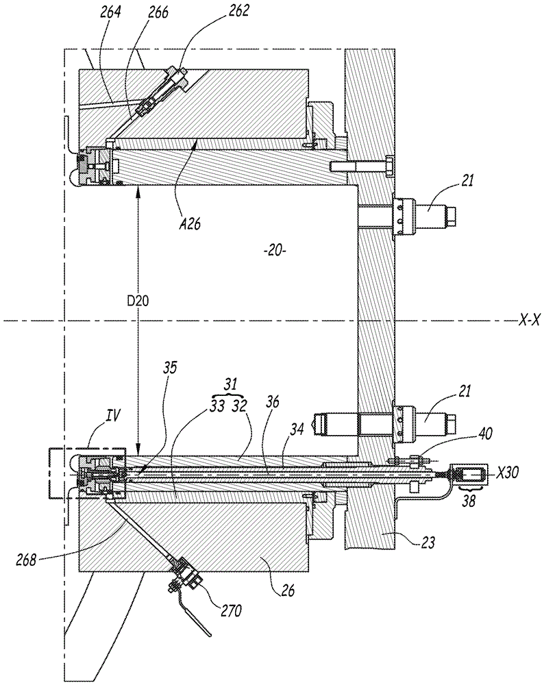
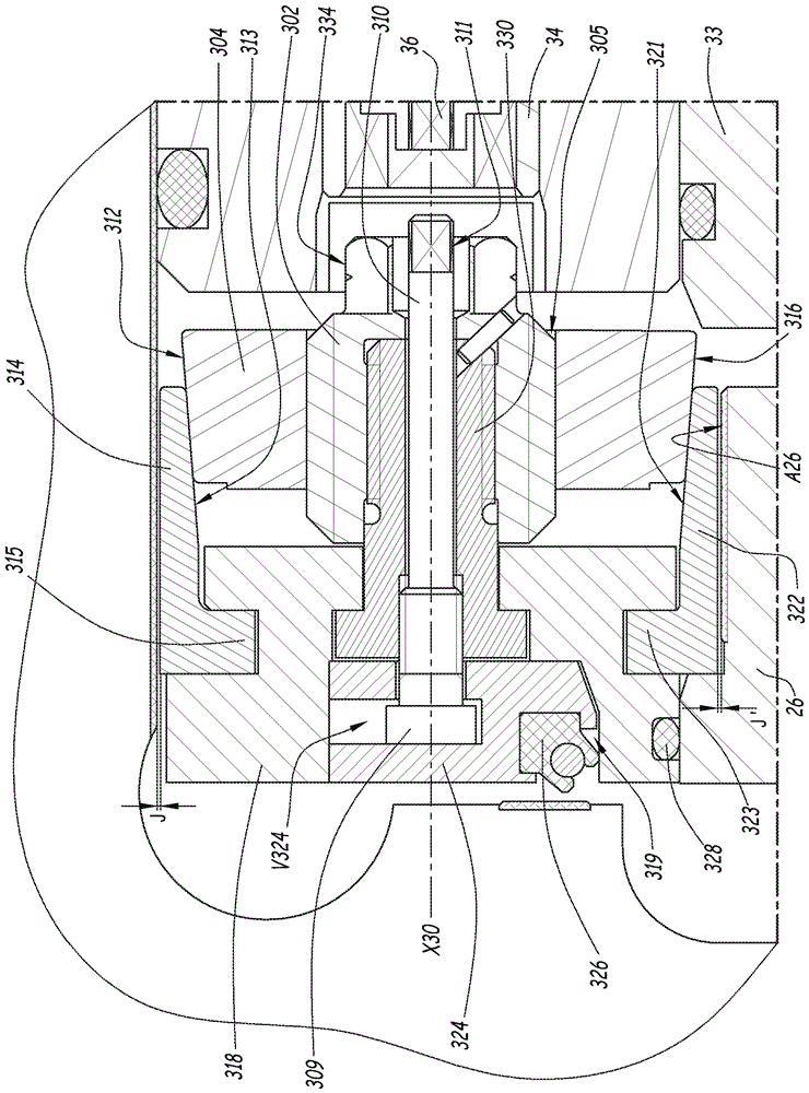
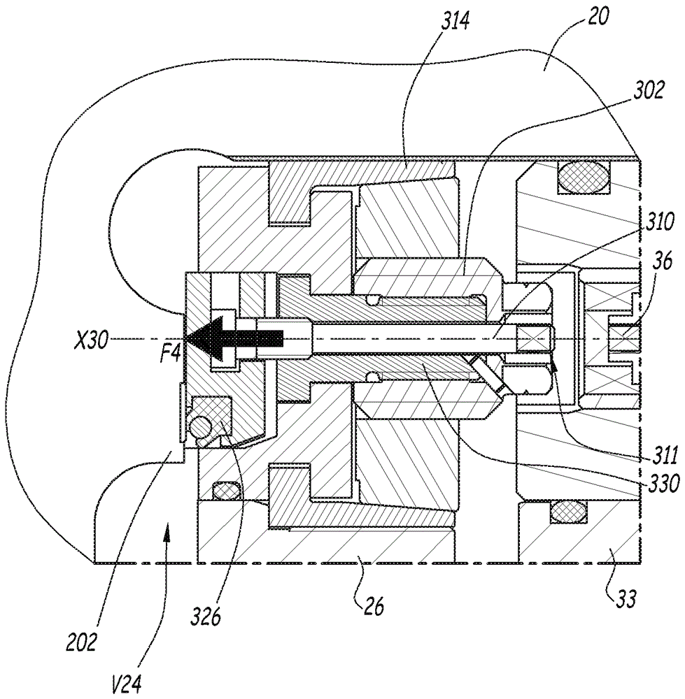
This valve (2) is integrated into a fluid distribution network and enables selective interruption or authorization of the circulation of a fluid; it includes a fluid blocking member driven in rotation by an actuator device of the valve and at least one journal (20), a hollow body (24) inside which the blocking member (22) is mobile and which defines at least one bore (A26) for receiving the journal (20), and a bearing (31) disposed around each journal (20) and inside the bore (A26) of the body (24) enabling support of the journal (20) and guidance thereof in rotation relative to the bore (A26), thereby centering the journal (20). The valve (2) further includes a device (30) for immobilizing and sealing for maintenance the journal relative to the body (22) of the valve (2), this immobilization device (30) being on the same side of the bearing (31) as the internal volume (V24) of the hollow body (24) and being maneuverable via the bearing (31) to go from a non-clamped first configuration to a clamped second configuration in which it immobilizes the journal (20) in the bore (A26) and vice versa.

Description

technical field [0001] The invention relates to a valve which, in the configuration of use, is integrated into a fluid distribution network, in particular on the upstream side of a hydraulic machine, and which is capable of interrupting or permitting the flow of fluid in a pipe in a controlled manner. A hydraulic machine means a turbine, a pump or a turbine-pump. Background technique [0002] Such valves include a component for blocking fluid called an obturator, which is driven in rotation by the valve's actuator to alternately block or permit the passage of fluid. Valves can be of the ball type, where the blocking member called the obturator has a spherical shape, or of the butterfly type, where the obturator is a simple disc. The obturator is journalled to the actuating means of the valve, enabling the transmission of rotational movement. The journal is thus in a receiving bore in the valve body. In addition, smooth bearings are used to support, guide and center each b...

Claims


Application Information

Patent Timeline
Patent Type & Authority Patents(China)
IPC IPC(8): F16K5/06F16K5/08F16K41/02F16K37/00
CPCF16K5/0647F16K5/08F16K43/00F16K5/0663F16K37/00Y10T137/0508Y10T137/8158
Inventor A.马蒂厄
Owner GE RENEWABLE TECH
Features
  • R&D
  • Intellectual Property
  • Life Sciences
  • Materials
  • Tech Scout
  • Unparalleled Data Quality
  • Higher Quality Content
  • 60% Fewer Hallucinations
Learn More