A c-band coupler with shielded wire

A shielded wire, C-band technology, used in waveguide-type devices, electrical components, connecting devices, etc., can solve the problems of unstable high and low temperature performance, narrow operating bandwidth, and poor consistency in mass production, and achieve stable high and low temperature performance. Working frequency bandwidth, the effect of solving large interference

Active Publication Date: 2017-12-01
NANJING UNIV OF POSTS & TELECOMM INST AT NANJING CO LTD
View PDF14 Cites 0 Cited by
  • Summary
  • Abstract
  • Description
  • Claims
  • Application Information

AI Technical Summary

Problems solved by technology

[0003] The invention aims to solve the technical problems of the traditional C-band coupler such as narrow working bandwidth, large loss, unstable high and low temperature performance, low processing accuracy, poor consistency in mass production, large volume, and heavy weight, so as to provide a The C-band coupler with shielded wire has the advantages of low loss, stable high and low temperature performance, high processing accuracy, good consistency in mass production, small size, and light weight.

Method used


Image

  • A c-band coupler with shielded wire
  • A c-band coupler with shielded wire
  • A c-band coupler with shielded wire

Examples


Embodiment Construction

[0024] The following describes the present invention in further detail with reference to the accompanying drawings and specific embodiments, without limiting the scope of implementation of the present invention.

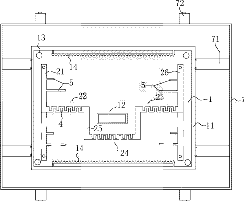
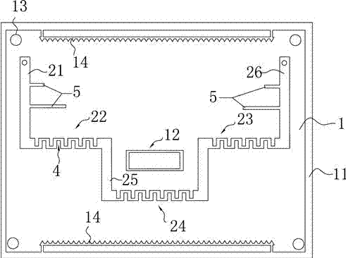
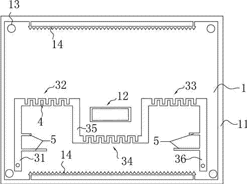
[0025] Such as Figure 1 to Figure 5 As shown, the C-band coupler with shielded wire described in this embodiment includes a metal shell 7, an insulating bridge 71 arranged in the metal shell 7, and a PCB board 1 arranged on the insulating bridge; The front side of the PCB board 1 is provided with a first input section 21 and a second input section 26. One end of the first input section 21 laterally extends to the side of the second input section 26 with a first coupling section 22, and the second input section A second coupling section 23 extends laterally from one end of the section 26 to the side of the first input section 21; the free ends of the first coupling section 22 and the second coupling section 23 respectively extend downwardly with a first connecting secti...


PUM


Abstract

The invention discloses a C-band coupler with shielded wires; through the three-segment coupling section distribution on the PCB, the problem of large interference of the traditional C-band bridge is effectively solved; in addition, because the coupling line is printed on the The PCB board is coupled through the insulating layer of the PCB board to realize integrated production, thereby realizing batch and simplified production, and improving the working frequency bandwidth, making it low loss and stable high and low temperature performance.

Description

Technical field [0001] The invention relates to a C-band coupler with shielded wire. Background technique [0002] The main structure of the C-band coupler is the shell and the built-in C-band bridge. At present, the existing C-band coupler is generally designed with electronic circuits. The wiring is complicated, the manufacturing is difficult, and the wiring is easy to make mistakes. When reducing the size, there are still shortcomings such as frequency mutual interference, and its electrical performance needs to be improved, such as narrow working bandwidth, large loss, unstable high and low temperature performance, etc., and there are also low processing accuracy, poor mass production consistency, Problems such as large size and heavy weight cannot meet the increasing requirements of broadband applications. Summary of the invention [0003] The invention aims to solve the technical problems of the traditional C-band coupler, such as narrow working bandwidth, large loss, unsta...

Claims


Application Information

Patent Timeline
Patent Type & Authority Patents(China)
IPC IPC(8): H01P5/18
Inventor 钟明乐
Owner NANJING UNIV OF POSTS & TELECOMM INST AT NANJING CO LTD
Why Eureka
Try Eureka