C-waveband coupler with shielded lines

A C-band, shielded wire technology, applied in the field of C-band couplers, can solve the problems of unstable high and low temperature performance, narrow working bandwidth, low processing accuracy, etc., achieve stable high and low temperature performance, improve the working frequency bandwidth, and realize batch the effect of

Active Publication Date: 2014-07-23
NANJING UNIV OF POSTS & TELECOMM INST AT NANJING CO LTD
View PDF14 Cites 0 Cited by
  • Summary
  • Abstract
  • Description
  • Claims
  • Application Information

AI Technical Summary

Problems solved by technology

[0003] The invention aims to solve the technical problems of the traditional C-band coupler such as narrow working bandwidth, large loss, unstable high and low temperature performance, low processing accuracy, poor consistency in mass production, large volume, and heavy weight, so as to provide a The C-band coupler with shielded wire has the advantages of low loss, stable high and low temperature performance, high processing accuracy, good consistency in mass production, small size, and light weight.

Method used


Image

  • C-waveband coupler with shielded lines
  • C-waveband coupler with shielded lines
  • C-waveband coupler with shielded lines

Examples


Embodiment Construction

[0024] The present invention will be described in further detail below in conjunction with the accompanying drawings and specific embodiments, and the implementation scope of the present invention is not limited thereto.

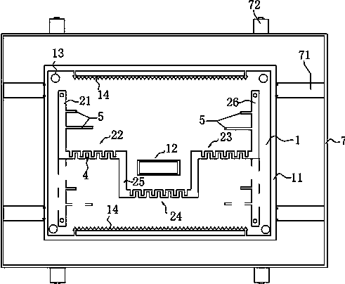
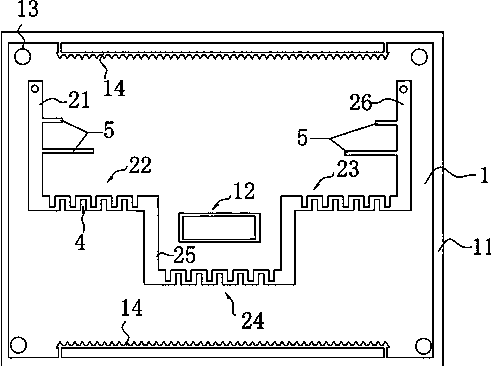
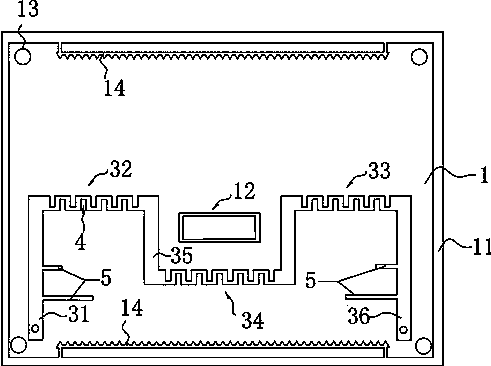
[0025] Such as Figure 1 to Figure 5 As shown, a C-band coupler with a shielded wire described in this embodiment includes a metal casing 7, an insulating bridge 71 disposed in the metal casing 7, and a PCB board 1 disposed on the insulating bridge; The front of the PCB board 1 is provided with a first input section 21 and a second input section 26, and one end of the first input section 21 extends laterally to the second input section 26 with a first coupling section 22, and the second input section One end of the segment 26 extends laterally toward the first input segment 21 with a second coupling segment 23; the free ends of the first coupling segment 22 and the second coupling segment 23 respectively extend downward with a first connecting segment 25, th...


PUM


Abstract

The invention discloses a C-waveband coupler with shielded lines. Through three-section-type distribution of coupling sections on a PCB, the problem that a traditional C-waveband electric bridge is large in interference is effectively solved. In addition, due to the fact that coupling lines are printed on the PCB and coupling is realized through an insulating layer of the PCB, integrated production is realized. Thus, mass and simple production is realized; moreover, the working bandwidth is increased, therefore, losses of the coupler are reduced and the high-temperature performance and the low-temperature performance of the coupler are stable.

Description

technical field [0001] The invention relates to a C-band coupler with a shielded wire. Background technique [0002] The main structure of the C-band coupler is the shell and the built-in C-band bridge. At present, the existing C-band couplers are generally designed with electronic circuits. When the size is reduced, there are still shortcomings such as frequency interference, and its electrical performance needs to be improved, such as narrow working bandwidth, large loss, unstable high and low temperature performance, etc., and there are also problems such as low processing accuracy, poor batch production consistency, Problems such as large size and heavy weight cannot meet the growing requirements of broadband applications. Contents of the invention [0003] The invention aims to solve the technical problems of the traditional C-band coupler such as narrow working bandwidth, large loss, unstable high and low temperature performance, low processing accuracy, poor consis...

Claims


Application Information

Patent Timeline
Patent Type & Authority Applications(China)
IPC IPC(8): H01P5/18
Inventor 赖耀华斯琴胡洁维
Owner NANJING UNIV OF POSTS & TELECOMM INST AT NANJING CO LTD
Why Eureka
Try Eureka