An upper vortex hole-driven swirling device for spud shoe lifting on an offshore drilling platform

A technology for offshore drilling platforms and spud shoes, which is applied in the direction of valve devices, valve operation/release devices, valve lifts, etc. Small and other problems, to achieve the effect of shortening the transfer cycle of the work area, speeding up the lifting, and improving the effect of spraying

Inactive Publication Date: 2016-08-24
齐宝兰
View PDF7 Cites 0 Cited by
  • Summary
  • Abstract
  • Description
  • Claims
  • Application Information

AI Technical Summary

Problems solved by technology

[0002] The direction of the water column ejected by the jetting head of the jetting device in the prior art is fixed, so the action range of the jetting sediment is distributed in a point line, and the jetting area is small, and it is impossible to quickly remove the adsorption of the seabed sediment to the outer surface of the spud can. Can not achieve the best rapid spray boost effect

Method used


Image

  • An upper vortex hole-driven swirling device for spud shoe lifting on an offshore drilling platform
  • An upper vortex hole-driven swirling device for spud shoe lifting on an offshore drilling platform
  • An upper vortex hole-driven swirling device for spud shoe lifting on an offshore drilling platform

Examples


Embodiment

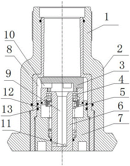
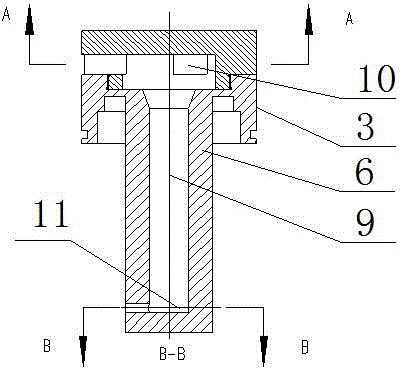
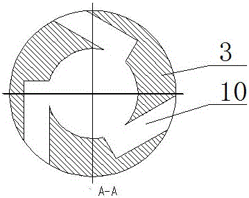
[0017] The spray flushing device working process of the present invention is as follows:

[0018] High-pressure water enters from the interface pipe, pushes the valve core to move down, the valve core moves down in conjunction with the valve stem, and the lower end of the valve stem protrudes from the end cover. High-pressure water enters the interface pipe and impacts the turbine water inlet hole in the middle of the valve core, driving the valve core to rotate. The water enters the vortex inlet hole and then enters the blind hole in the center of the valve stem, and then rotates along the blind hole from the punching hole at the lower end of the valve stem to form a disc surface. When the high-pressure water in the mouthpiece is closed, the valve stem follows the valve. When the core moves up, the spraying hole at the lower end of the valve stem retracts upwards in the middle hole of the end cap, the spraying hole is closed, and the spraying cleaning operation is terminated. ...


PUM


Abstract

The invention provides an upper vortex-hole driven rotary spray device for spud shoe lifting of an offshore drilling platform. The structure includes a casing, a valve core, a valve stem, an end cover and a return spring. The upper end of the valve is provided with an interface pipe, the lumen of the interface pipe communicates with the valve chamber, the lower end of the valve chamber is connected with an end cap through threads, and a through hole is vertically opened in the center of the end cap, and the top edge of the valve core is connected with the lower nozzle of the interface pipe. The lower end of the valve core is provided with a valve stem, the center of the valve stem is opened with a blind hole, the middle of the upper part of the valve core is horizontally opened with a vortex water inlet hole, and the lower end of the valve stem is opened with a spray hole through which the spray hole passes. The blind hole communicates with the vortex inlet hole. The outer circle of the lower end of the valve stem passes through the vertical through hole in the center of the end cover. The outer circle of the valve stem is covered with a return spring. The upper end of the valve core is connected with the thrust bearing at the bottom of the spool. The valve core rotates automatically during the spraying process, changing the point-line spraying of the existing technology to rotating surface spraying, which increases the spraying area, improves the spraying effect, speeds up the lifting of the spud can, and shortens the working area of ​​the oil platform transfer cycle.

Description

technical field [0001] The invention relates to the technical field of offshore oil drilling platforms, in particular to an upper vortex hole-driven swirling device for spud shoe lifting of the offshore drilling platform. Background technique [0002] The direction of the water column sprayed out by the jetting head of the jetting device in the prior art is fixed, so the action range of the jetting sediment is distributed in a point line, and the jetting area is small, and it is impossible to quickly remove the adsorption of the seabed sediment on the outer surface of the spud can. Can not reach the best rapid spraying and boosting effect. Contents of the invention [0003] The technical task of the present invention is to solve the deficiencies of the prior art, and provide an upper vortex hole-driven swirling device for spud shoe lifting of an offshore drilling platform. [0004] The technical solution of the present invention is realized in the following manner. The ro...

Claims


Application Information

Patent Timeline
Patent Type & Authority Patents(China)
IPC IPC(8): E02D13/08F16K1/00F16K1/36F16K31/12
Inventor 齐宝兰
Owner 齐宝兰
Why Eureka
Try Eureka