Supercharge Your Innovation With Domain-Expert AI Agents!

Water tank drain valve with water leakage detection function

A drainage valve and water level detection technology, which is applied to flushing equipment with water tanks, water supply devices, buildings, etc., can solve problems such as difficulty in finding detection and solutions, large amount of wasted water, and drainage

Inactive Publication Date: 2015-05-20
陈焕忠
View PDF11 Cites 0 Cited by
  • Summary
  • Abstract
  • Description
  • Claims
  • Application Information

AI Technical Summary

Problems solved by technology

In the above two situations, no matter which situation occurs, it will cause water to be released day and night, and the amount of wasted water will be large
But on the other hand, since the toilet water tank itself needs the function of normal drainage, it has been difficult to find a suitable detection and solution for the problem of water leakage in the toilet water tank

Method used


Image

  • Water tank drain valve with water leakage detection function
  • Water tank drain valve with water leakage detection function
  • Water tank drain valve with water leakage detection function

Examples


Embodiment 1

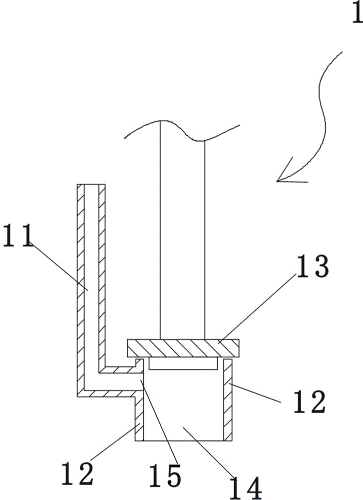
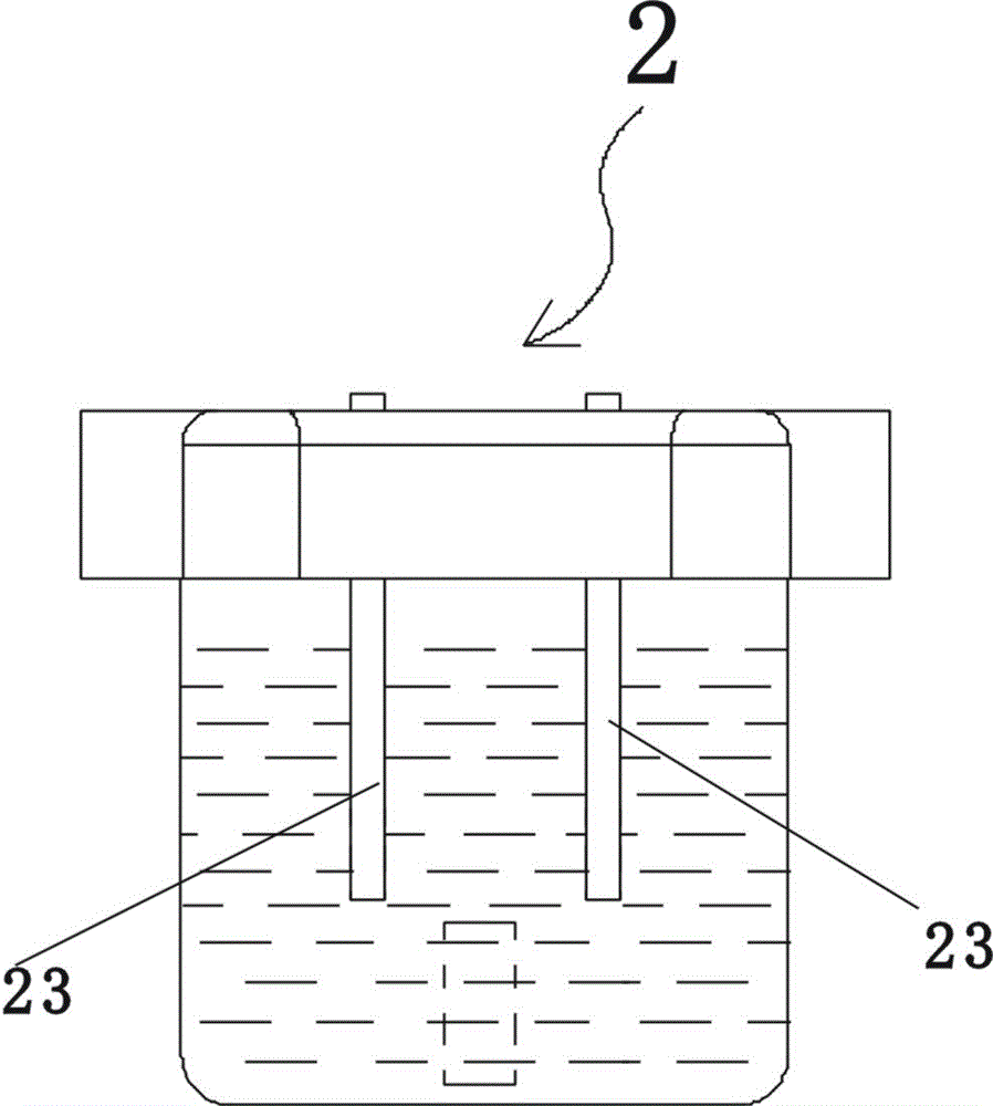
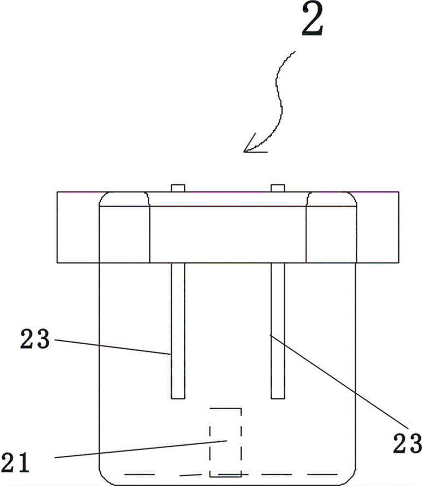
[0037] Figure 7 , Figure 14 , Figure 15 , Figure 16 , Figure 17 , image 3 , figure 2 As shown, the water tank drain valve with water leakage detection function in this embodiment includes a valve body 1, the valve body is provided with an overflow pipe 11, an annular base 12, a valve cover 13, and a valve cover control for controlling the opening or closing of the valve cover. Mechanism, the bonnet control mechanism is the same as the traditional technology, the center of the ring-shaped base 12 forms a drain 14, and the valve cover 13 is movable to cover the top of the drain 14 of the ring-shaped base; the ring-shaped base 12 is provided with an overflow hole 15. The lower end of the overflow pipe 11 communicates with the overflow hole 15; a water storage cylinder 2 and a water guide groove 4 are arranged in the drain outlet 14, and the horizontal projection shape of the water guide groove 4 is arc-shaped, and the water guide groove 4 is close to the ring shape T...

Embodiment 2

[0051] In this embodiment, the horizontal projection shape of the water guide groove is circular, the water guide groove is close to the inner surface of the circular base, and the vertical position of the water guide groove is lower than the vertical position of the overflow hole, and the water guide groove is provided with Align the notch on the water inlet of the water storage cylinder. In this way, no matter the valve cover is not tightly closed and the water leaks, or the water inlet channel leaks, the water flow will continuously flow into the water guide groove, and continue to flow into the water inlet of the water storage tank through the gap of the water guide groove, and finally the inner cavity of the water storage tank will continue to accumulate water. In addition, in the second embodiment, only the lowest point of one metal contact is higher than the lowest point of the small water discharge hole of the water storage cylinder, and the lowest point of the other me...


PUM


Abstract

The invention discloses a water tank drain valve with a water leakage detection function. The water tank drain valve comprises a valve body, wherein an overflow pipe, an annular base and a valve deck are arranged on the valve body; a drainage opening is formed in the center of the annular base; an overflow hole is formed in the annular base; a water storage barrel and a water guide groove are arranged in the drainage opening; the water guide groove is formed and extends in a position close to the inside surface of the annular base; a water inlet is formed in the upper part of the water storage barrel; a small drainage hole is formed in the lower part of the water storage barrel; the discharge area of the water inlet of the water storage barrel is greater than that of the small drainage hole; the cavity of the water guide groove is communicated with the water inlet in the upper part of the water storage barrel; a water level detection switch is arranged in the inner cavity of the water storage barrel; a microprocessor is also arranged outside the drain valve body; the water level detection switch is connected to the microprocessor through a first signal wire; the microprocessor monitors the time length t1 of the water level detection switch lastingly in the connected state; the microprocessor is also connected with a feedback executing mechanism through a second signal wire. The water tank drain valve can automatically detect the leakage of the water tank, and commands the feedback executing mechanism to act.

Description

technical field [0001] The invention belongs to a water tank drain valve used for toilets, in particular to a water tank drain valve with a water leakage detection function. Background technique [0002] Toilet water tanks are all provided with water inlet channels and drain valves, wherein the drain valves are responsible for controlling flushing, and the water inlet channels are responsible for replenishing water to the water tanks. figure 1 , figure 2 , image 3 As shown, the drain valve of the toilet tank includes a valve body 1, the valve body of the drain valve is provided with an overflow pipe 11, an annular base 12, a valve cover 13, and a valve cover control mechanism, and the center of the annular base forms a drain port 14 , the bonnet 13 movable cover is closed on the top of the drain port 14 of the annular base, and the bonnet control mechanism controls the opening or closing of the bonnet; the annular base is also provided with an overflow hole 15, and the l...

Claims


Application Information

Patent Timeline
Patent Type & Authority Patents(China)
IPC IPC(8): E03D1/34
Inventor 陈焕忠
Owner 陈焕忠
Features
  • R&D
  • Intellectual Property
  • Life Sciences
  • Materials
  • Tech Scout
  • Unparalleled Data Quality
  • Higher Quality Content
  • 60% Fewer Hallucinations
Learn More