Method for erecting long crane jibs

A crane and boom technology, applied in the field of mobile cranes or crawler cranes, can solve problems such as falling back and achieve the effect of increasing the stability moment

Active Publication Date: 2017-08-29
LIEBHERR WERK EHINGEN
View PDF10 Cites 0 Cited by
  • Summary
  • Abstract
  • Description
  • Claims
  • Application Information

AI Technical Summary

Problems solved by technology

[0006] However, in the solutions mentioned above, it is disadvantageous that during the fully erecting operation of the lower boom section, the upper boom section must be secured against the boom falling back due to the inclined erecting angle

Method used


Image

  • Method for erecting long crane jibs
  • Method for erecting long crane jibs
  • Method for erecting long crane jibs

Examples


Embodiment Construction

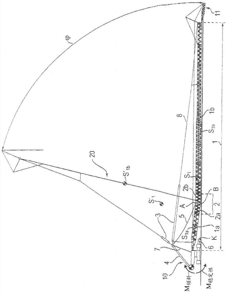
[0034] figure 1 Shown is a mobile crane 10 with a liftable main boom 1 comprising a lower boom section 1 a and an upper boom section 1 b which are pivotally connected to each other about an articulation point A . exist figure 1 In , the overall boom length of the main boom 1 is set based on the ground. The main boom 1 comprises a specific intermediate piece 2 which is inserted instead of the standard intermediate piece. Theoretically, the insertion of the intermediate piece 2 can be carried out at any point of the main boom 1 .

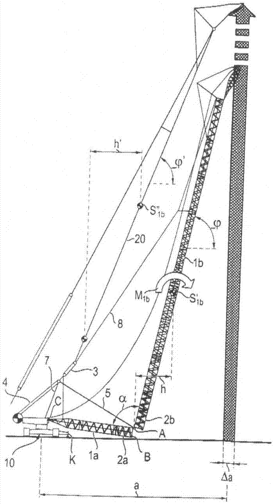
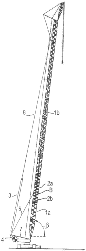
[0035]The middle part 2 consists of a lower part 2a and an upper part 2b, wherein the lower part 2a is connected to the lower boom section 1a and the upper part 2b is connected to the upper boom section 1b. At point A, the upper part 2b and the lower part 2a are pivotally connected to each other. At point B, a connection can also be established between the upper part 2b and the lower part 2a to form a rigid connection between the boom section 1a a...


PUM


Abstract

The method involves erecting the upper boom segment (1b) to a determined angle opposite to the horizontal, where the lower boom segment (1a) is erected, at the same time the upper boom segment is controlled depending on the crane projection. The upper boom segment is controlled, so that the projection remains constant during the erection and lies in a certain tolerance range. An independent claim is included for a crane with a crane controller.

Description

technical field [0001] The invention relates to a method for erecting a long two-piece crane jib, and a crane, in particular a mobile crane or a crawler crane, with a long main jib and a crane controller for carrying out such a method type crane. Background technique [0002] The invention mainly relates to a crane comprising a one-piece jib consisting of individual lattice pieces firmly screwed to each other. For special areas of application, mobile cranes require increasingly longer booms. In particular, during the construction of wind turbines, there is the problem of having to erect very long booms. Due to such a long jib, the crane must maintain an exceptionally high moment during jib erection. [0003] Accordingly, such jibs are usually erected with an attached lifting jib with a suspended superlift counterweight. However, this is very time consuming and difficult to operate in the uneven terrain on which wind turbines are often located. [0004] Therefore, for th...

Claims


Application Information

Patent Timeline
Patent Type & Authority Patents(China)
IPC IPC(8): B66C23/82
CPCB66C23/82
Inventor 安德烈亚斯·奥尔良
Owner LIEBHERR WERK EHINGEN
Why Eureka
Try Eureka