
LED failure detection system

A detection system and technology of LED light groups, applied in the field of LED, can solve problems such as increased cost, failure of light-emitting diodes, and inability to work.

Inactive Publication Date: 2014-08-20
ANHUI ZHAOLI OPTO ELECTRONICS TECH
View PDF0 Cites 7 Cited by
  • Summary
  • Abstract
  • Description
  • Claims
  • Application Information

AI Technical Summary

Problems solved by technology

Due to long-term use, some light-emitting diodes in the light-emitting diode array will fail to work, which will affect the use effect of the entire light-emitting diode array
For this situation, in the past, only the LED array was replaced as a whole, which will greatly increase the cost

Method used


Image

  • LED failure detection system

Examples


Embodiment Construction

[0010] The present invention will be described in detail below in conjunction with the accompanying drawings and specific embodiments.

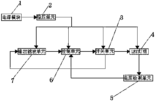
[0011] like figure 1 As shown, an LED failure detection system includes a power module, a switch unit, an LED lamp group, a voltage detection unit, a control unit, and an output filter unit. The power module is respectively connected to the switch unit, the LED lamp group, and the voltage detection unit, control unit and output filter unit, the output end of the output filter unit is connected to the input end of the control unit, the output end of the control unit is connected to the input end of the switch unit, the first output end of the switch unit is connected to the LED light group, the second The two output terminals are connected to the output filter unit; the LED lamp group is connected to the control unit through the voltage detection unit.

[0012] The voltage detection unit includes a single-chip microcomputer, and the single-ch...


PUM


Abstract

Disclosed is an LED failure detection system. The LED failure detection system comprises a power module, a switch unit, an LED lamp set, a voltage detection unit, a control unit and an output filtering unit. The power module is respectively connected with the switch unit, the LED lamp set, the voltage detection unit, the control unit and the output filtering unit through a voltage stabilization unit, the output end of the output filtering unit is connected with the input end of the control unit, the output end of the control unit is connected with the input end of the switch unit, the first output end of the switch unit is connected with the LED lamp set, the second output end of the switch unit is connected with the output filtering unit, and the LED lamp set is connected with the control unit through the voltage detection unit. The LED failure detection system can effectively perform LED failure detection on an LED and can ensure that the failure number of LEDs in an LED array can be effectively counted no matter the LEDs are at open circuit failure states or at short circuit failure states.

Description

technical field [0001] The invention relates to the technical field of LEDs, in particular to an LED failure detection system. Background technique [0002] With the rapid development of semiconductor technology, light-emitting diodes (LEDs) have been widely used in products such as lighting, light-emitting displays and indications. Due to the characteristics of light-emitting diodes, they are generally arranged in arrays when they are used, so as to achieve good use effects. Specific such as road lights, various advertising signs and so on. Due to long-term use, some light-emitting diodes in the light-emitting diode array may fail to work, which affects the use effect of the entire light-emitting diode array. In the past, the only way to solve this situation is to replace the LED array as a whole, which will greatly increase the cost. Contents of the invention [0003] The object of the present invention is to provide an LED failure detection system to solve the above ...

Claims


Application Information

Patent Timeline
IPC IPC(8): G01R31/26
Inventor 胡学军邬国平江严宝汪旭欧阳锋
Owner ANHUI ZHAOLI OPTO ELECTRONICS TECH
Learn More