UPS parallel system and counter synchronization signal receiving method
A technology for synchronizing signals and receiving methods, applied in the field of control, can solve the problems of inconsistent output power, the same power-on time, and it is difficult to chop the same count value of the counter, so as to improve the stability of the power supply, improve the consistency, and reduce the high voltage. The effect of frequency circulation
- Summary
- Abstract
- Description
- Claims
- Application Information
AI Technical Summary
Problems solved by technology
Method used
Image

Examples
Embodiment 1
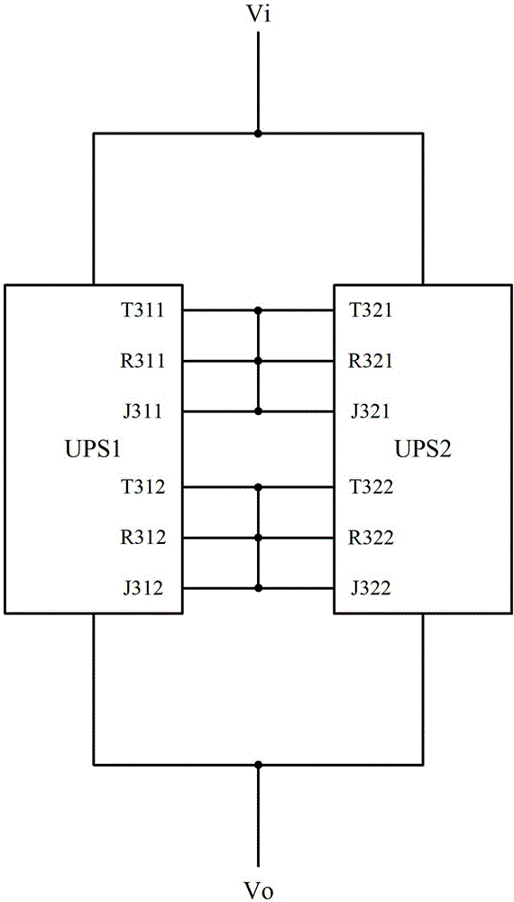
[0047] image 3 Shown is the structure diagram of the UPS parallel system provided by Embodiment 1 of the present invention, specifically including UPS1 and UPS2, each UPS includes two sending ports, two receiving ports and two judging ports respectively, Vi is the UPS power input terminal, Vo is the output terminal of UPS power supply, where:
[0048] The first receiving port R311 of UPS1 is connected to its own first sending port T311, and is connected to the first sending port T321 of UPS2; the first judging port J311 of UPS1 is connected to its own first sending port T311, and is connected to the first sending port T311 of UPS2. A sending port T321 is connected; the second receiving port R312 of UPS1 is connected to its own second sending port T312, and is connected to the second sending port T322 of UPS2; the second judgment port J312 of UPS1 is connected to its own second sending port T312 , and connected to the second sending port T322 of UPS2. Correspondingly, the fi...
Embodiment 2
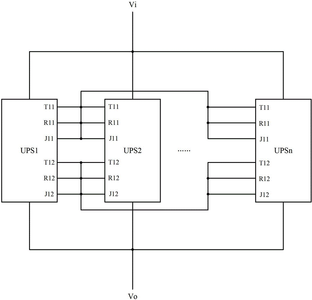
[0062] Figure 4 Shown is the structure diagram of the UPS parallel system provided by Embodiment 2 of the present invention, specifically including UPS1 and UPS2, each UPS includes n sending ports, n receiving ports and n judging ports respectively, n is greater than 2, and Vi is the UPS Power input terminal, Vo is UPS power output terminal, where:
[0063] The first receiving port R411 of UPS1 is connected to its own first sending port T411, and is connected to the first sending port T421 of UPS2; the first judging port J411 of UPS1 is connected to its own first sending port T411, and is connected to the first sending port T411 of UPS2. A sending port T421 is connected; the second receiving port R412 of UPS1 is connected to its own second sending port T412, and is connected to the second sending port T422 of UPS2; the second judgment port J412 of UPS1 is connected to its own second sending port T412 , and connected to the second sending port T422 of UPS2... The nth receivin...
Embodiment 3
[0076] Figure 7 Shown is the structure diagram of the UPS parallel system provided by Embodiment 3 of the present invention, specifically including UPS1 and UPS2, each UPS includes two sending ports and two receiving ports respectively, Vi is the UPS power input terminal, and Vo is the UPS power output end, where:
[0077] The first receiving port R711 of UPS1 is connected to its own first sending port T711, and is connected to the first sending port T721 of UPS2; the second receiving port R712 of UPS1 is connected to its own second sending port T712, and is connected to the first sending port T721 of UPS2. The two sending ports T722 are connected. Correspondingly, the first receiving port R721 of UPS2 is connected to its own first sending port T721, and is connected to the first sending port T711 of UPS1; the second receiving port R722 of UPS2 is connected to its own second sending port T722, and is connected to The second sending port T712 of UPS1 is connected.
[0078] ...
PUM
 Abstract
Description
Claims
Application Information
 - R&D
- Intellectual Property
- Life Sciences
- Materials
- Tech Scout
- Unparalleled Data Quality
- Higher Quality Content
- 60% Fewer Hallucinations
Browse by: Latest US Patents, China's latest patents, Technical Efficacy Thesaurus, Application Domain, Technology Topic, Popular Technical Reports.
© 2025 PatSnap. All rights reserved.Legal|Privacy policy|Modern Slavery Act Transparency Statement|Sitemap|About US| Contact US: help@patsnap.com