A Method for Restraining Air Bubble Interference by Photoelectric Direct Reading Water Meter Sensor

A photoelectric sensor, photoelectric direct reading technology, applied in the direction of volume indication and recording equipment, etc., can solve the problems of low precision, refraction, sensor coding error, etc., to achieve the effect of easy implementation and simple program operation

Active Publication Date: 2017-09-26
深圳市骏普科技开发有限公司
View PDF6 Cites 0 Cited by
  • Summary
  • Abstract
  • Description
  • Claims
  • Application Information

AI Technical Summary

Problems solved by technology

With the development of technology, photoelectric direct reading technology has developed rapidly in recent years. Due to the addition of a first-level magnetic sensor to the water metering drive of the dry water meter, the accuracy is low, and its flow rate will decrease over time. The measurement accuracy is getting lower and lower, which also affects the use and promotion of dry meters; however, the existing photoelectric direct-reading sensors for wet water meters have obvious shortcomings: bubbles are prone to occur in the liquid seal box of wet water meters, especially When there are air bubbles on the coding strip or in the coding groove, when the light emitted by the light emitting tube passes through, refraction and other phenomena are likely to occur, which reduces the light intensity irradiated to the light receiving tube, reduces the induced current of the light receiving tube, and causes the sensor Coding errors lead to reading errors due to air bubble interference; for air bubble interference, there is currently no effective way in the industry. Due to the limitation of air bubble interference, the promotion of photoelectric direct-reading wet water meters is difficult

Method used


Image

  • A Method for Restraining Air Bubble Interference by Photoelectric Direct Reading Water Meter Sensor

Examples


Embodiment Construction

[0021] Below in conjunction with accompanying drawing, the present invention will be further described:

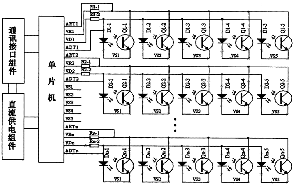
[0022] like figure 1 Shown: the method for suppressing bubble interference provided by the photoelectric direct-reading water meter sensor provided in this embodiment includes a single-chip microcomputer, a communication interface component, a DC power supply component, and multiple groups of photoelectric sensors composed of multiple pairs of photosensitive receiving tubes and light emitting tubes. sensor decoder component, the figure 1 Among them, a photoelectric sensor composed of 5 pairs of photosensitive receiving tubes and a pair of light emitting tubes is used, and a photoelectric sensor decoder is composed of n groups of photoelectric sensors. The photoelectric sensor decoder provides a detailed electrical principle connection diagram. figure 1 Among them, Dn-m, and Qn-m (m represents the marked number of 1-5) form a pair of light emitting tubes, photosensitive re...


PUM


Abstract

A method for suppressing bubble interference by photoelectric direct-reading water meter sensors, suitable for water meters that use photoelectric technology to encode and output electrical signals for the readings displayed by mechanical counters, including single-chip microcomputers, communication interface components, DC power supply components, and multiple pairs of photosensitive receivers The photoelectric sensor decoder component of the photoelectric sensor composed of tubes and light emitting tubes to tubes, the I / O port of the microcontroller connected to the photosensitive receiving tube has a programmable output function and an input function with a pull-up. By switching the port to The output function and the input function with pull-up complete the different power supply connections to the photosensitive receiving tube, so that the sampling resistor of the photosensitive receiving tube is connected in series with a single external sampling resistor (Rn‑1) and the external sampling resistor (Rn‑1). The pull-up resistor (R) of the internal I / O port is switched, and the sensing sensitivity of the photosensitive receiving tube is adjusted by adjusting the sampling resistance of the photosensitive receiving tube to realize the function of suppressing bubble interference. It has strong anti-bubble interference ability and low cost , implementing simple features.

Description

Technical field: [0001] The invention relates to a method for suppressing air bubble interference by a photoelectric direct-reading water meter sensor, which is suitable for a water meter that adopts photoelectric technology to code and output an electrical signal for readings displayed by a mechanical counter, especially a photoelectric direct-reading wet water meter. Background technique: [0002] Water meters are divided into two categories: dry water meters and wet water meters. At present, automatic remote meter reading technology has emerged a device that reads the reading information of a meter by adding a photoelectric sensor component, that is, a photoelectric direct-reading sensor device, referred to as photoelectric. Direct reading sensor. The device makes a technical transformation on the counter character wheel of the original mechanical counter device, and makes code strips on the counter character wheel according to a certain coding rule. The number is conver...

Claims


Application Information

Patent Timeline
Patent Type & Authority Patents(China)
IPC IPC(8): G01F15/06
Inventor 吴明星陈守平李祖斌刘颖华何兰资广泰
Owner 深圳市骏普科技开发有限公司
Why Eureka
Try Eureka