Check patentability & draft patents in minutes with Patsnap Eureka AI!

Terminal structure

A technology of terminal structure and microstructure, which is applied in the direction of fixed connection, circuit, connection, etc., and can solve problems such as poor contact, high cost, and small scraping area

Active Publication Date: 2014-08-27
DELTA ELECTRONICS INC
View PDF5 Cites 4 Cited by
  • Summary
  • Abstract
  • Description
  • Claims
  • Application Information

AI Technical Summary

Problems solved by technology

[0003] However, the insulating varnish material of the general wire has high heat resistance, and it is difficult to be broken by soldering. It needs to be scraped off with a jig, but the cost is high. The current method is to use the friction force when the wire is combined with the terminal structure. Directly scrape off the insulating varnish of the wire, and at the same time make the two electrically connected, but the current practice, the area that can be scraped off is small, once the exposed conductive material is oxidized, it will cause poor contact

Method used


Image

  • Terminal structure
  • Terminal structure
  • Terminal structure

Examples


Embodiment Construction

[0042] A terminal structure according to a preferred embodiment of the present invention will be described below with reference to the related drawings, wherein the same elements will be described with the same reference symbols. It should be noted that the accompanying drawings are only schematic representations, and do not represent actual dimensions and proportions. In practice, the dimensions and proportions can be designed in different ways according to needs.

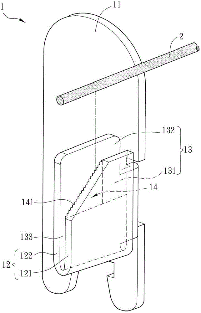
[0043] Please refer to figure 1 As shown, it is a schematic diagram of a terminal structure 1 according to a preferred embodiment of the present invention. In practice, the terminal structure 1 can be used with a circuit board (not shown) and one or more wires 2 , wherein the wires 2 can be polyester enamelled wire (PEW), the surface of which is coated with a layer of Insulating paint to protect the conductive material inside from damage. The terminal structure 1 can be used to electrically connect the circuit b...


PUM


Abstract

A terminal structure comprises a base, a connecting part, a clamping part and a first scraping part. The connecting part is connected with the base, is U-shaped, and comprises a first end and a second end. The clamping part comprises a first clamping plate and a second clamping plate, the first clamping plate is connected with the first end of the connecting part, the second clamping plate is connected with the second end of the connecting part, and a slit is formed between a surface of the first clamping plate and a surface of the second clamping plate. The first scraping part is connected with one edge of the first clamping plate and the first end of the connecting part. The first scraping part has a first bevel edge which tilts towards the first end from the top edge of the first clamping plate.

Description

technical field [0001] The present invention relates to a terminal structure. Background technique [0002] With the development of the electronics industry, the application of motors can be seen everywhere in people's lives. In the structure of the motor, the electrical connection between the wire (such as enameled wire) and the circuit board needs to be achieved through a terminal structure, in which the wire conducts electricity. The periphery of the material (such as copper wire) is usually covered with a layer of insulating varnish to protect the conductive material from being damaged by moisture in the air or other factors. In this case, if the wire passes through the terminal structure and the circuit board For electrical connection, it is necessary to strip off the insulating paint covered on the periphery of the wire. [0003] However, the insulating varnish of the general wire has high heat resistance, and it is difficult to be broken by solder, and it needs to be...

Claims


Application Information

Patent Timeline
IPC IPC(8): H01R12/53H01R12/55
Inventor 陈孟钰陈弘琪钱汉恩
Owner DELTA ELECTRONICS INC
Features
  • R&D
  • Intellectual Property
  • Life Sciences
  • Materials
  • Tech Scout
  • Unparalleled Data Quality
  • Higher Quality Content
  • 60% Fewer Hallucinations
Learn More