Wire pressing plate

A technology of crimping boards and line segments, which is applied in the field of crimping boards and can solve problems such as the overall volume of wire slots becoming smaller

Inactive Publication Date: 2014-09-10
SUZHOU HTS MOLD
View PDF5 Cites 3 Cited by
  • Summary
  • Abstract
  • Description
  • Claims
  • Application Information

AI Technical Summary

Problems solved by technology

The existing crimping plate is a straight plate, installed in the wire groove, and the screws used for fixing also need to be trapped in the wire groove, so the overall volume of the wire groove will become smaller, and the wires that can be accommodated are relatively small

Method used


Image

  • Wire pressing plate
  • Wire pressing plate
  • Wire pressing plate

Examples


Embodiment Construction

[0014] The preferred embodiments of the present invention will be described in detail below in conjunction with the accompanying drawings, so that the advantages and features of the present invention can be more easily understood by those skilled in the art, so as to define the protection scope of the present invention more clearly.

[0015] see Figure 1 to Figure 4 , the embodiment of the present invention includes:

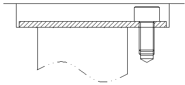
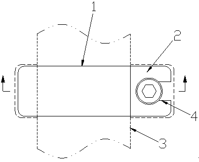
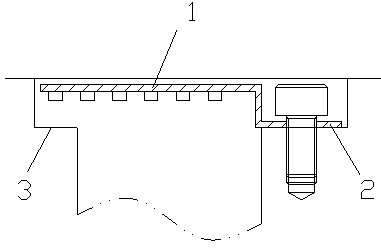
[0016] In one embodiment, a crimping plate is installed on the wire groove 3 by screws, the crimping plate is divided into a crimping section 1 and a fixing section 2, the crimping section 1 is higher than the fixing section 2, and the fixing section The section 2 is provided with a mounting hole 4; the line pressing section 1 is in an "L" shape, and the inner wall of the line pressing section 1 is provided with a card slot. Such as image 3 As shown, compared with the wire crimping plate in the prior art, the raised “L” shaped crimping plate can maximize the...


PUM


Abstract

The invention discloses a wire pressing plate which includes a wire pressing section and a fixing section. The wire pressing section is higher than the fixing section. An installation hole is arranged in the fixing section. The wire pressing plate is capable of accommodating more wires under a condition that the width of a wire groove is not increased and the narrower the wire groove is, the better the strength is.

Description

technical field [0001] The invention relates to the field of crimping tools, in particular to a crimping plate. Background technique [0002] The wire crimping plate is used to cover the wire groove, which can shield and protect the wires in the wire groove, and is also more beautiful. The existing wire crimping plate is a straight plate, installed in the wire groove, and the screws used for fixing also need to be trapped in the wire groove, so the overall volume of the wire groove will become smaller, and the wires that can be accommodated are relatively small. Contents of the invention [0003] The technical problem mainly solved by the present invention is to provide a wire crimping plate, which can accommodate more wires without increasing the width of the wire slot, and the narrower the wire slot, the better the strength. [0004] In order to solve the above technical problems, a technical solution adopted by the present invention is to provide a crimping plate, the ...

Claims


Application Information

Patent Timeline
Patent Type & Authority Applications(China)
IPC IPC(8): H02G3/04
Inventor 严杰
Owner SUZHOU HTS MOLD
Why Eureka
Try Eureka