Movable pay-off rack

A technology of pay-off frame and support plate, which is applied in the direction of cable layout between relative moving parts, electrical components, cable installation, etc., can solve the problems of poor flexibility of use, cumbersome process, and inability to move the pay-off frame, and achieve improved Work efficiency, flexible movement, convenient and fast wiring

Inactive Publication Date: 2014-09-10
JIANGSU JIACHENG TECH
View PDF5 Cites 0 Cited by
  • Summary
  • Abstract
  • Description
  • Claims
  • Application Information

AI Technical Summary

Problems solved by technology

In actual work, due to the lack of professional equipment, heavy cables need to be hoisted by a crane or everyone works together to erect them on the pay-off rack. The process is cumbersome, and ordinary pay-off racks cannot be moved, and the use flexibility is poor.

Method used


Image

  • Movable pay-off rack

Examples


Embodiment Construction

[0014] The following will clearly and completely describe the technical solutions in the embodiments of the present invention. Obviously, the described embodiments are only some of the embodiments of the present invention, rather than all the embodiments. Based on the embodiments of the present invention, all other embodiments obtained by persons of ordinary skill in the art without making creative efforts belong to the protection scope of the present invention.

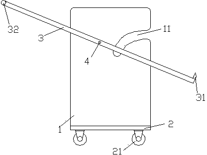
[0015] see figure 1 , the embodiment of the present invention includes:

[0016] A mobile pay-off frame, comprising: a vertical support plate 1, a fixed base 2 and a rotating lever 3, the vertical support plate 1 is symmetrically arranged on both sides of the upper surface of the fixed base 2, and the rotating lever 3 is respectively arranged On the outside of the vertical support plate 1, the middle part of the rotating lever 3 is provided with a pin 4 connected to the vertical supporting plate 1, so that the rotat...


PUM


Abstract

The invention discloses a movable pay-off rack. The movable pay-off rack comprises vertical support plates, a fixing bottom seat and rotation levers, wherein the vertical support plates are respectively and symmetrically arranged on two sides of the upper surface of the fixing bottom seat, the rotation levers are respectively arranged on the outer sides of the vertical support plates, pin shaft connected with the vertical support plates are arranged in the middles of the rotation levers, arc sliding chutes are respectively formed in the vertical support plates, and rolling vehicle wheels are arranged on the lower portion of the fixing bottom seat. By adopting the mode, the movable pay-off rack uses the rotation levers to feed cable reels to the arc sliding chutes, conveniently and rapidly performs wiring, and is flexible to move and improves work efficiency of site pay-off operation due to the fact that the universal vehicle wheels are arranged at the bottom of the movable pay-off rack.

Description

technical field [0001] The invention relates to the field of cable pay-off frame design, in particular to a mobile pay-off frame. Background technique [0002] Cables and wires are generally composed of three components: core wire, insulating sheath and protective sheath. In order to facilitate storage and transportation, cables and wires are packaged into rolls during production, and each roll of cable is provided with a cable of a certain length and weight. . [0003] When laying out wires or cables, the packaged coils need to be unwound first, and when the coiled cables are unwound, in order to reduce the work intensity, they need to be placed on the pay-off frame for rotation to unwind smoothly. In actual work, due to the lack of professional equipment, heavy cables need to be hoisted by a crane or everyone can work together to erect them on the pay-off rack. Contents of the invention [0004] The technical problem mainly solved by the present invention is to provide...

Claims


Application Information

Patent Timeline
Patent Type & Authority Applications(China)
IPC IPC(8): H02G11/00
Inventor 张军
Owner JIANGSU JIACHENG TECH
Why Eureka
Try Eureka