Method for controlling fuel injection system

A fuel injection system and internal combustion engine technology, applied in fuel injection pumps, fuel injection devices, fuel injection control, etc., can solve problems such as high cost, and achieve the effect of shortening start-up time and restart time

Inactive Publication Date: 2014-09-17
ROBERT BOSCH GMBH
View PDF5 Cites 4 Cited by
  • Summary
  • Abstract
  • Description
  • Claims
  • Application Information

AI Technical Summary

Problems solved by technology

This additional device is also associated with higher costs

Method used


Image

  • Method for controlling fuel injection system
  • Method for controlling fuel injection system
  • Method for controlling fuel injection system

Examples


Embodiment Construction

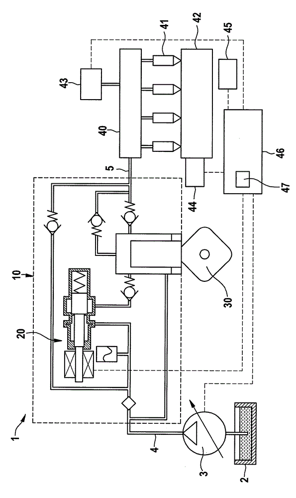
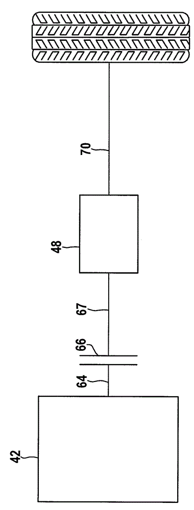
[0027] figure 1 A schematic diagram of a fuel injection system 1 of an internal combustion engine 42 with start-stop function is shown. The fuel injection system comprises a fuel container 2 from which a pre-feed pump 3 pumps fuel via a line 4 with a corresponding pre-feed pressure to a high-pressure fuel pump 10 driven via a cam 30 . A flow control valve 20 is arranged on the high-pressure pump 10 on the low-pressure side. The delivery volume of the high-pressure pump 10 is set by means of the flow control valve 20 . The cam 30 is driven by the internal combustion engine 42 , for example by an associated motor shaft, and can also be a component thereof. This motor shaft is figure 2 is explained in detail and marked with 64.

[0028] The high-pressure pump 10 preferably has a delivery chamber with a non-return valve arranged on the inlet side. The high-pressure pump compresses the fuel to a particularly high pressure and conveys it via a line 5 into a high-pressure accum...


PUM


Abstract

The invention relates to a method for controlling a fuel injection system of an internal combustion engine of a motor vehicle with a start stopping function. The fuel injection system comprises a high pressure pump (10). A pre-supplying pump (3) supplies fuel to the high pressure pump. During a stopping period, under the condition that the pressure is lower than a pre-selected minimum pressure of a high pressure storage device (40) loaded in a pressure mode by the high pressure pump (10), a motor shaft of the internal combustion engine carries out a revolution to operate a cam (30) in effect connection with the motor shaft, and the high pressure pump (10) can be driven by the help of the cam.

Description

technical field [0001] The invention relates to a method for controlling a fuel injection system of a start-stop function (start-stop-funktion) internal combustion engine, wherein the fuel injection system comprises a high-pressure pump which is supplied with fuel by a pre-supply pump . Background technique [0002] Internal combustion engines with a so-called start-stop function are known from the prior art. Such internal combustion engines are usually automatically switched off during a standstill in order to reduce consumption or save fuel by an injection suppression. To switch on the internal combustion engine again, a restart request is generated, for example by the user of the internal combustion engine, so that a starter assigned to the internal combustion engine is actuated in order to carry out a new starting process by turning the starter. [0003] In such internal combustion engines, the reactivation after a stop phase is usually dependent on the generated start...

Claims


Application Information

Patent Timeline
Patent Type & Authority Applications(China)
IPC IPC(8): F02D45/00F02D41/38B60W20/00
CPCF02D41/38F02D45/00B60W20/00B60W30/18018B60W20/40B60Y2300/48F02D41/042F02D41/123F02D41/3845F02D2250/31F02M59/102F02M59/367F02M63/0265F02N99/006
Inventor N.米勒J.金佩尔P.申克C.胡松格
Owner ROBERT BOSCH GMBH
Why Eureka
Try Eureka