Drive control of power system including fuel cells

a technology of power system and fuel cell, which is applied in the direction of battery/fuel cell control arrangement, electrochemical generators, transportation and packaging, etc., can solve the problems of increasing the size of the whole system, frequent temporary stoppage and significant energy loss, so as to shorten the restart time of fuel gas generation systems and reduce potential energy loss in power systems.

Inactive Publication Date: 2009-03-10
TOYOTA JIDOSHA KK
View PDF12 Cites 3 Cited by
  • Summary
  • Abstract
  • Description
  • Claims
  • Application Information

AI Technical Summary

Benefits of technology

[0008]The object of the invention is thus to shorten a restart time of a fuel gas generation system and reduce a potential energy loss in a power system, which includes fuel cells and the fuel gas generation system that generates a fuel gas to be supplied to the fuel cells.

Problems solved by technology

On the vehicle, however, the fuel gas generation system is subjected to frequent temporary stops, for example, during a stop at a traffic light and during a drive on a downslope.
Removal of hydrogen from the hydrogen separator unit at every temporary stop undesirably lengthens a restart time of the system and causes a significant energy loss.
The presence of the hydrogen reservoir, however, undesirably increases the size of the whole system and complicates the system configuration.

Method used


Image

  • Drive control of power system including fuel cells
  • Drive control of power system including fuel cells
  • Drive control of power system including fuel cells

Examples


second embodiment

C. Second Embodiment

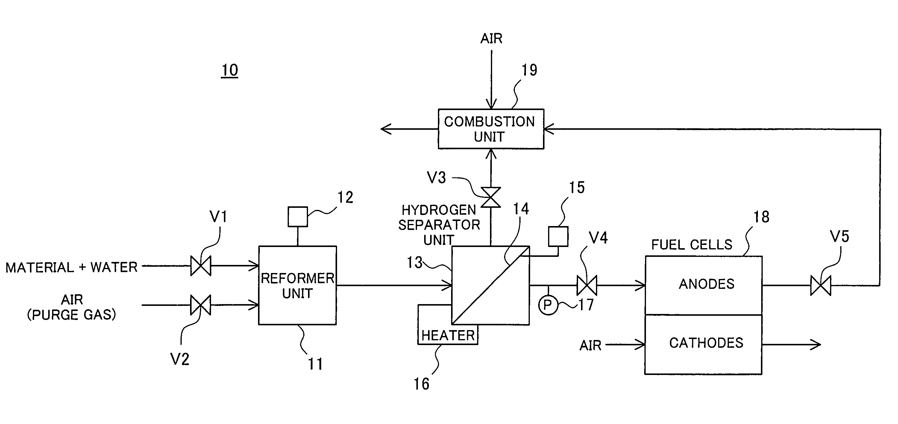
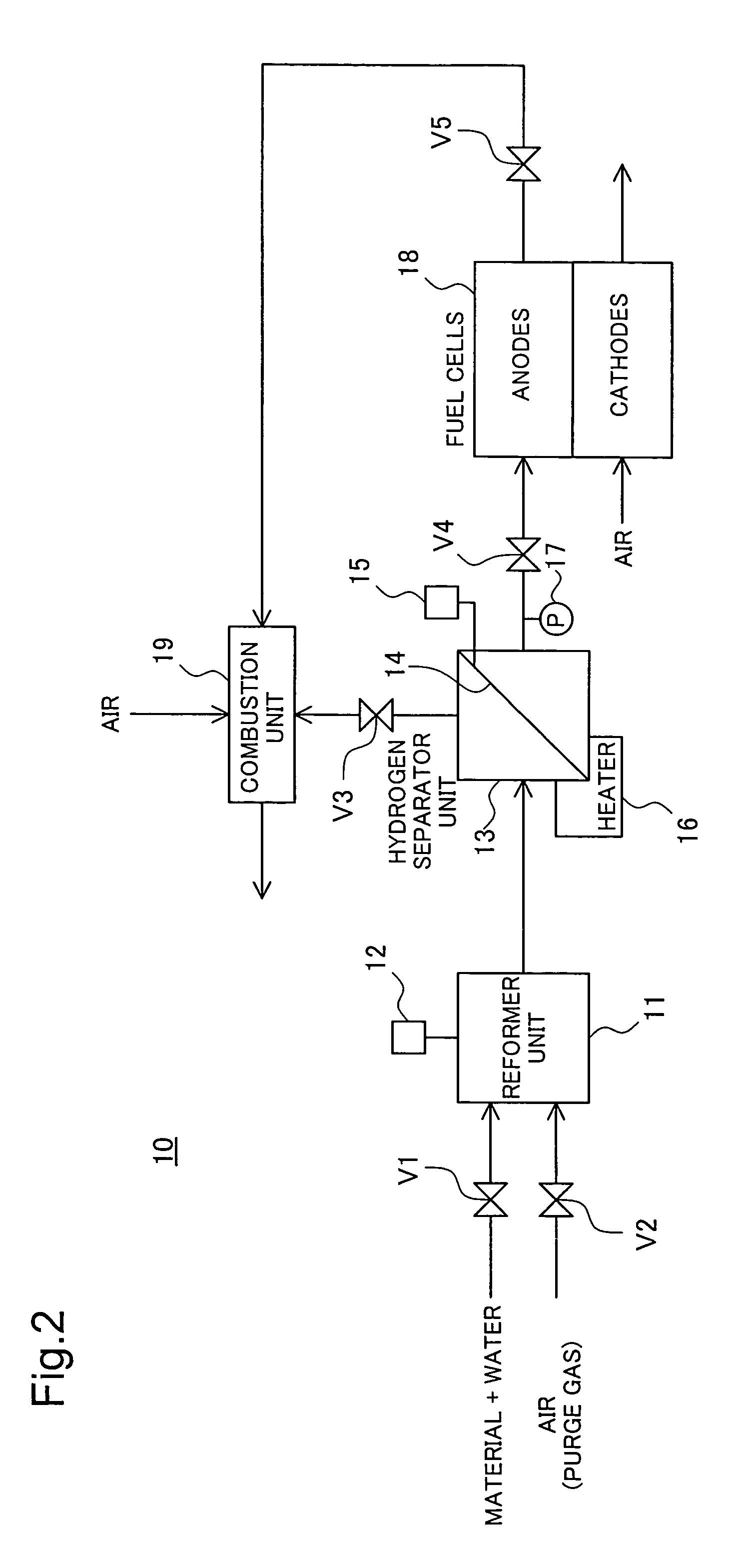
[0125]The fuel cell system 10 of the first embodiment has the electric heater 16, which is activated to heat the hydrogen separation membrane 14 in the pause process. The structure of a second embodiment does not have the electric heater 16 and is otherwise similar to that of the first embodiment. The flow of the drive control process executed in the second embodiment is similar to that in the first embodiment, except the control in the pause process as discussed below.

[0126]FIG. 10 is a flowchart showing a pause process executed in the second embodiment. The CPU first changes over the open-closed positions of the valves V1 through V5 to those in ‘State A’ shown in the table of FIG. 11 (step S510a) and purges the non-reformed gas in the reformer unit 11 and hydrogen in the hydrogen separator unit 13. Here the purge gas is supplied at a fixed flow rate. When a time period Tr since the start of the pause process reaches a reference time Tr_ref2 (step S520a), the CP...

modified example 1

D1. Modified Example 1

[0129]In the above embodiment, the control decision process shown in the flowchart of FIG. 5 sets the respective flags according to the various conditions. These conditions and their combination may be set arbitrarily.

modified example 2

D2. Modified Example 2

[0130]The procedure of the above embodiment selects either the pause process or the stop process at the start of the stop control of the fuel gas generation system. One possible modification may omit such selection but may unconditionally execute the pause process and then change over the stop control to the stop process based on the various parameters.


PUM

PropertyMeasurementUnit
temperature measurementaaaaaaaaaa
temperatureaaaaaaaaaa
timeaaaaaaaaaa

Abstract

A power system of the invention includes fuel cells and a fuel gas generation system that generates a fuel gas to be supplied to the fuel cells. At the time of stopping supply of hydrogen, the fuel gas generation system selectively uses a stop process that replaces hydrogen in a hydrogen separator unit with the air for removal of hydrogen and a pause process that allows hydrogen to remain in the hydrogen separator unit. The stop process is selected when the fuel gas generation system stops the supply of hydrogen for a long time period. The pause process is selected when the fuel gas generation system temporarily stops the supply of hydrogen. The arrangement of the invention desirably shortens a restart time of the fuel gas generation system and reduces a potential energy loss.

Description

BACKGROUND OF THE INVENTION[0001]1. Field of the Invention[0002]The present invention relates to a drive control technique of a power system including fuel cells.[0003]2. Description of the Related Art[0004]Various power systems have been developed and proposed, which include fuel cells and a fuel gas generation system for generating a fuel gas to be supplied to the fuel cells and output electric power. In some type of the known fuel gas generation systems, a reformer reforms a material like gasoline or methanol to produce a hydrogen-containing gaseous mixture and a hydrogen separator unit with a hydrogen separation membrane extracts hydrogen from the gaseous mixture.[0005]In this known fuel gas generation system with the hydrogen separation membrane, some techniques of removing hydrogen from the hydrogen separator unit at a stop of the system have been proposed to prevent hydrogen brittleness of the hydrogen separation membrane (for example, see Patent Laid-Open Gazette No. 2001-11...

Claims


Application Information

Patent Timeline
Patent Type & Authority Patents(United States)
IPC IPC(8): H01M8/18H01M8/04H01M8/12H01M8/00B60L11/18C01B3/02H01M8/06H01M8/10H01M16/00
CPCB60L58/31H01M8/04231H01M8/0432H01M8/04373H01M8/04753H01M8/04947H01M8/0612H01M16/006Y02E60/10Y02E60/50Y02T90/40
Inventor AOYAMA, SATOSHIOGINO, SHIGERUIZAWA, YASUHIROIGUCHI, SATOSHIMASUI, TAKATOSHI
Owner TOYOTA JIDOSHA KK
Why Eureka
Try Eureka