Damper device

一种减振器、变速器的技术,应用在控制装置、传动装置、齿轮传动装置等方向,能够解决抑制发动机扭转振动、消除减振器装置共振点、调整减振器装置质量或弹簧常数难等问题,达到提高衰减特性的效果

Inactive Publication Date: 2014-09-17
SUBARU CORP
View PDF11 Cites 5 Cited by
  • Summary
  • Abstract
  • Description
  • Claims
  • Application Information

AI Technical Summary

Problems solved by technology

However, not only is it difficult to adjust the mass and spring constant of the damper device, but it is also difficult to eliminate the resonance point of the damper device in a wide range from the low speed range to the high speed range.
Therefore, in the case of using the existing damper device, it is difficult to suppress the torsional vibration of the engine in a wide range

Method used


Image

  • Damper device
  • Damper device
  • Damper device

Examples


Embodiment Construction

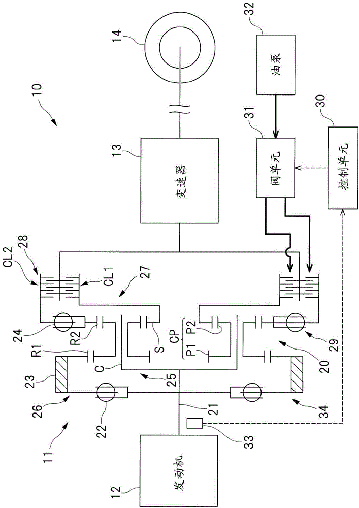
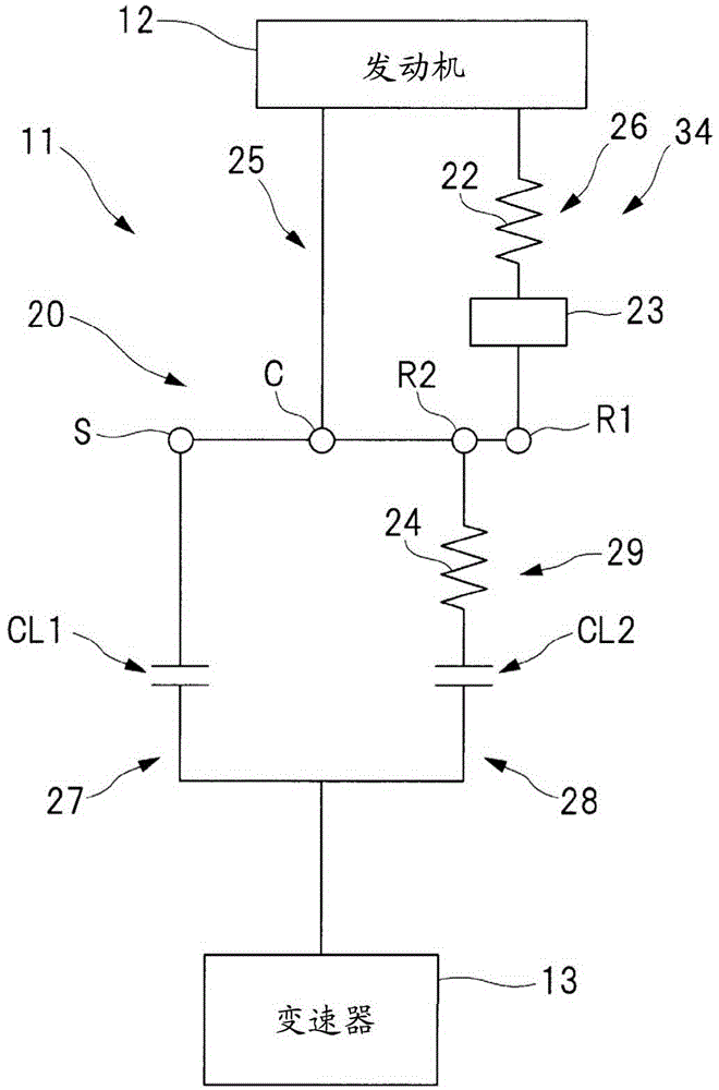
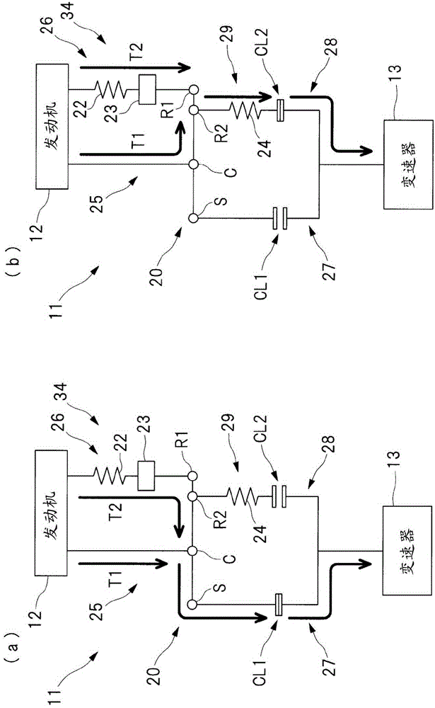
[0074] Hereinafter, embodiments of the present invention will be described in detail based on the drawings. figure 1 It is a schematic diagram showing a power unit 10 including the damper device according to the first embodiment of the present invention. exist figure 1 The shown power unit 10 incorporates a damper device 11 according to one embodiment of the present invention. in addition, figure 2 It is an explanatory diagram showing a structural model of the damper device 11 incorporated in the power unit 10 . in addition, image 3 (a) and (b) are explanatory diagrams showing the state of engine torque transmission. like figure 1 The drive unit 10 shown has an engine 12 as an internal combustion engine and a transmission 13 connected to the engine 12 via a damper arrangement 11 . In this way, the damper device 11 is provided between the engine 12 and the transmission 13 , and the torsional vibration caused by the excitation force of the engine 12 is attenuated using t...


PUM


Abstract

The invention relates to a damper device for inhibiting torsional vibration of an engine in a broad range. A damper device (11) is provided between the engine (12) and a transmission (13) and has a torque distribution mechanism (20) that is provided with a bracket C connected to the engine (12), a first gear ring (R1) connected to the engine (12) via a first elastic member (22), a sun gear S connected to the transmission (13), and a second gear ring (R2) connected to the transmission (13) via a second elastic member (24). The damper device (11) further has a first clutch (CL1) that is provided between the sun gear (S) and the transmission (13) that is switched between an engaged state of connecting the sun gear (S) and the transmission (13) and a released state of disconnecting the sun gear (S) from the transmission (13) and a second clutch (CL2) that is provided between the second gear ring (R2) and the transmission (13) and that is switched between an engaged state of connecting the second gear ring (R2) to the transmission (13) and a released state of disconnecting the second gear ring (R2) from the transmission.

Description

technical field [0001] The present invention relates to a damper device provided between an engine and a transmission. Background technique [0002] In order to reduce the torsional vibration transmitted from the engine to the transmission, a damper device is provided between the engine and the transmission. As such a damper device, a damper device including two flywheels connected via a spring has been proposed (see Patent Document 1). [0003] In this way, by connecting the two flywheels via the spring, torsional vibration of the engine can be suppressed. [0004] prior art literature [0005] Patent Literature [0006] Patent Document 1: International Publication WO2012 / 66680 [0007] On the other hand, the damper device is designed so that the resonance point (natural frequency) of the damper device can be eliminated from the normal range of the engine speed by adjusting the mass or spring constant of the components constituting the damper device. However, not only ...

Claims


Application Information

Patent Timeline
Patent Type & Authority Applications(China)
IPC IPC(8): F16F15/131F16H57/028F16H3/44
CPCY10T477/753F16F15/1478F16D48/062F16D2500/3067F16D2500/50293F16D2500/525F16F15/1206F16H47/08B60K17/3467F16H1/28F16D13/385
Inventor 右近靖幸村上守铃木雄树筱原刚
Owner SUBARU CORP
Why Eureka
Try Eureka