Ceiling type range hood

A range hood, top suction technology, applied in the direction of removing oil fume, heating method, household heating, etc., can solve the problems of low smoking efficiency, inconvenient disassembly and assembly, etc., to enhance the ability to absorb oil fume, convenient and quick disassembly, assembly and use handy effect

Inactive Publication Date: 2014-10-08
浙江森歌智能厨电股份有限公司
View PDF6 Cites 40 Cited by
  • Summary
  • Abstract
  • Description
  • Claims
  • Application Information

AI Technical Summary

Problems solved by technology

It solves the problem of the prior art that oil fume can only enter the air inlet from the other three sides, the sm

Method used


Image

  • Ceiling type range hood
  • Ceiling type range hood
  • Ceiling type range hood

Examples


Embodiment 1

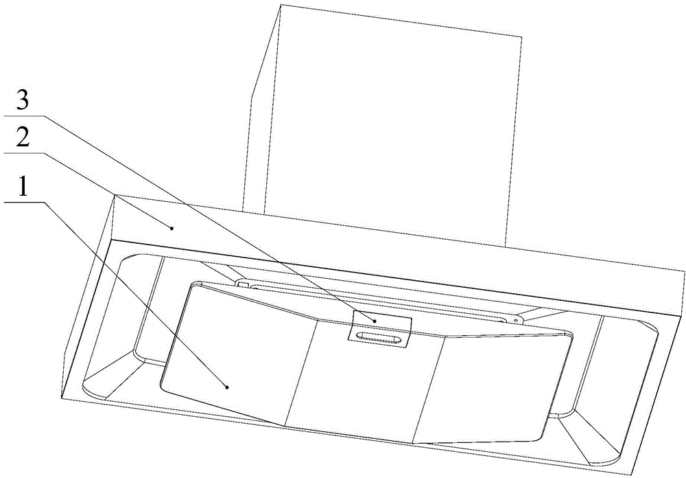
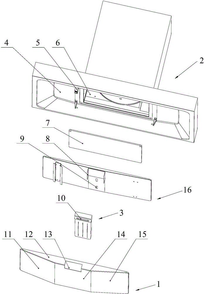
[0031] Such as figure 1 , 2 As shown, a top-suction range hood includes a smoke collection hood 2 and an air inlet 6 arranged on the bottom surface 4 of the smoke collection hood, and also includes:

[0032] Safety net 7 is arranged on the air inlet;

[0033] The oil collecting plate 16 is arranged directly below the air inlet, and is fixed with the bracket 5 fixed on the bottom surface 4 of the smoke collecting hood. The oil collecting plate and the bottom surface where the air inlet is located form four side air intake passages, and the middle part of the oil collecting plate is concave And the lower recess has an oil outlet 9;

[0034] The shroud 1 is arranged on the lower surface of the oil collecting plate;

[0035] The extractable oil collecting box 3 is arranged on the shroud, and the open end of the extractable oil collecting box is opposite to the oil outlet.

[0036] Such as figure 2 As shown, the wind deflector 1 includes a bottom plate 14 and a front wall pla...

Embodiment 2

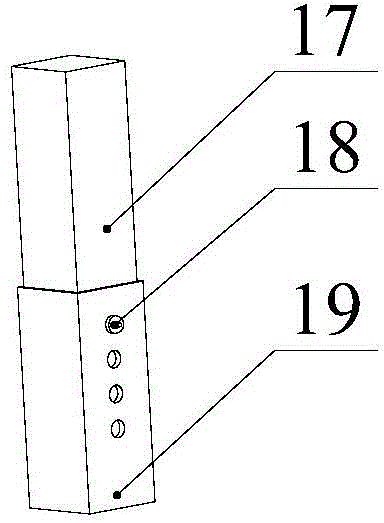
[0040] The bracket in this embodiment is an adjustable bracket, and other structures are consistent with Embodiment 1.

[0041] Such as image 3 As shown, the adjustable support includes an upper frame 17 and a lower frame 19 that are slidably inserted, and a positioning pin 18 is arranged between the upper frame and the lower frame. The height of the channel is the distance between the oil collecting plate and the bottom surface of the smoke collecting hood, that is, the height of the adjustable bracket. By adjusting the corresponding upper and lower shelves, the height of the channel can be adjusted, making the range hood more applicable when installing Strong, can adjust the height of the channel according to the specific situation, to ensure that the range hood has the greatest range hood effect.

[0042] The invention can guide the oil fume through the guide cover, and guide the oil fume to all directions of the channel. Because the channel is four-sided air intake, the ...


PUM


Abstract

The invention discloses a ceiling type range hood, which comprises a smoke collection hood, an air inlet formed in the bottom surface of the smoke collection hood, an oil collection plate, a flow guide hood and a drawing type oil collection box, wherein the oil collection plate is fixed right below the air inlet and forms a channel available for air to inflow in four sides with the bottom surface in which the air inlet is formed; an oil outlet is formed in the middle of the oil collection plate; the flow guide hood covers the lower surface of the oil collection plate; the drawing type oil collection box is arranged on the flow guide hood and is opposite to the oil outlet in position. According to the ceiling type range hood, air can enter from four sides and the smoke suction efficiency is relatively high; by arranging the drawing type oil collection box, collection of relatively large amount of oil drops can be guaranteed, the drawing type oil collection box can be conveniently and rapidly dismounted and the use is convenient; four side plates of the flow guide hood are obliquely arranged, so that oil fume can be guided from four directions and the oil fume suction capability of the range hood is enhanced to the greatest extent; by forming a stressed groove or a stressed pulling block in the bottom surface of the drawing type oil collection box, a user can find a force point while operating so as to conveniently draw out the drawing type oil collection box.

Description

technical field [0001] The invention relates to the field of household appliances, in particular to a top-suction range hood. Background technique [0002] Range hoods are essential kitchen equipment for modern families. Especially when Chinese families process food, they often use methods such as frying, frying, cooking, and deep-frying that will generate a lot of oily fumes. The kitchen environment becomes greasy and difficult to clean. Range hoods are a powerful weapon to improve the kitchen environment. [0003] The working principle of the range hood is as follows: After the power is turned on, the motor drives the impeller to rotate at a high speed, forming a negative pressure area in a certain space above the stove, sucking the indoor fume gas into the inner wall of the range hood, and filtering the fume gas through the oil screen , carry out the first oil fume separation, and then enter the inside of the hood air duct, and carry out the second oil fume separation on...

Claims


Application Information

Patent Timeline
IPC IPC(8): F24C15/20
Inventor 范德忠李林
Owner 浙江森歌智能厨电股份有限公司
Why Eureka
Try Eureka