Negative-pressure-free water supply equipment

A water supply equipment, no negative pressure technology, applied in the field of box-type non-negative pressure water supply equipment, can solve the problems of poor energy saving effect, large water pressure fluctuation and high installation strength

Inactive Publication Date: 2014-10-15
SHANGHAI PANDA MACHINEGRP CO LTD
View PDF7 Cites 0 Cited by
  • Summary
  • Abstract
  • Description
  • Claims
  • Application Information

AI Technical Summary

Problems solved by technology

[0002] The box-type non-negative pressure water supply equipment in the prior art generally has two structural modes. One is to install a small booster pump and a stacked pump in series at the water outlet of the water tank to solve the problem of boosting the water in the tank when the tap water has negative pressure. Finally, to meet the flow requirements of the stack pump, the head of the stack pump can be reduced by subtracting the tap water pressure to reduce the power, but the disadvantages of this method are high manufacturing cost, high installation strength, difficult control method, and large water pressure fluctuations
Another way is not to configure a booster pump. The power of the stacked pump is increased according to the full head configuration. When the tap water generates negative pressure, the stacked pump is switched to the water tank to absorb water. This way can reduce the configuration of the booster pump, but the pump runs In two working conditions (water inlet with pressure and no pressure), the energy saving effect of the pump is not as good as the first one when it is running

Method used


Image

  • Negative-pressure-free water supply equipment

Examples


Embodiment Construction

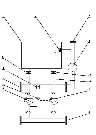
[0007] Such as figure 1 The non-negative pressure water supply equipment shown includes: water tank 1, superimposed pump group 2, tap water protection device 3, hydraulic switching device 4, solenoid valve 8, control cabinet (marked in the figure) and valves, superimposed pump The water inlet of group 2 is connected to the water inlet main pipe 6, and the tap water is connected to the water tank 1 and the water inlet main pipe 6 after passing through the tap water protection device 3 and the float valve 5 through the interface 7. The number of pumps in the stacked pump group 2 can be adjusted according to the system flow Set multiple sets of different sizes, the water outlet of the superimposed pump group 2 is connected to the water outlet main pipe 9, the user water pipe is connected to the water outlet main pipe 9, the spare pump 10 in the superimposed pump group 2 is selected as the booster pump, and the hydraulic switch is installed on the water inlet main pipe 6 The devic...


PUM


Abstract

The invention provides negative-pressure-free water supply equipment. When the equipment works and the pressure of tap water is normal, a solenoid valve is at a closed position, and a three-way type hydraulic conversion device is opened to communicate a water inlet manifold, so that all pumps in a pump set can be used for supplying water to users through overlapping pressure of the tap water; when the pressure of the tap water cannot meet the utilization of the pressure overlapped pump set, a spare pump in the pump set is automatically controlled by a system to play a role of a booster pump, the solenoid valve is switched on, and the booster pump starts to work; the pressure of the booster pump enforces the three-way type hydraulic conversion device to be closed so that the booster pump can be used for boosting reserved water in a water tank and supplying the water to the pressure overlapped pump with the tap water through the three-way type hydraulic conversion device at the same time, so as to overcome a phenomenon that the pressure of the tap water is not enough; the operation condition of the pressure overlapped pump basically keeps unchanged and the aim of saving energy is realized.

Description

technical field [0001] The invention relates to a non-negative pressure water supply equipment, in particular to a box-type non-negative pressure water supply equipment. Background technique [0002] The box-type non-negative pressure water supply equipment in the prior art generally has two structural modes. One is to install a small booster pump and a stacked pump in series at the water outlet of the water tank to solve the problem of boosting the water in the tank when the tap water has negative pressure. Finally, to meet the flow requirements of the stack pump, the head of the stack pump can be reduced by subtracting the tap water pressure to reduce the power, but the disadvantages of this method are high manufacturing cost, high installation strength, difficult control method, and large water pressure fluctuations. Another way is not to configure a booster pump. The power of the stacked pump is increased according to the full head configuration. When the tap water gener...

Claims


Application Information

Patent Timeline
Patent Type & Authority Applications(China)
IPC IPC(8): E03B11/16
Inventor 池学聪谭红全
Owner SHANGHAI PANDA MACHINEGRP CO LTD
Why Eureka
Try Eureka