Refrigeration cycle device

A refrigeration cycle and refrigerant technology, applied in the direction of refrigerators, refrigeration components, refrigeration and liquefaction, etc., can solve the problem that the filter is not easy to set, and achieve the effect of good shunt characteristics

Active Publication Date: 2014-10-29
HITACHI JOHNSON CONTROLS AIR CONDITIONING INC
View PDF7 Cites 5 Cited by
  • Summary
  • Abstract
  • Description
  • Claims
  • Application Information

AI Technical Summary

Problems solved by technology

However, according to the structure of the expansion valve described in the above patent document, the installation of the filter is not easy.

Method used


Image

  • Refrigeration cycle device
  • Refrigeration cycle device
  • Refrigeration cycle device

Examples


Embodiment 1

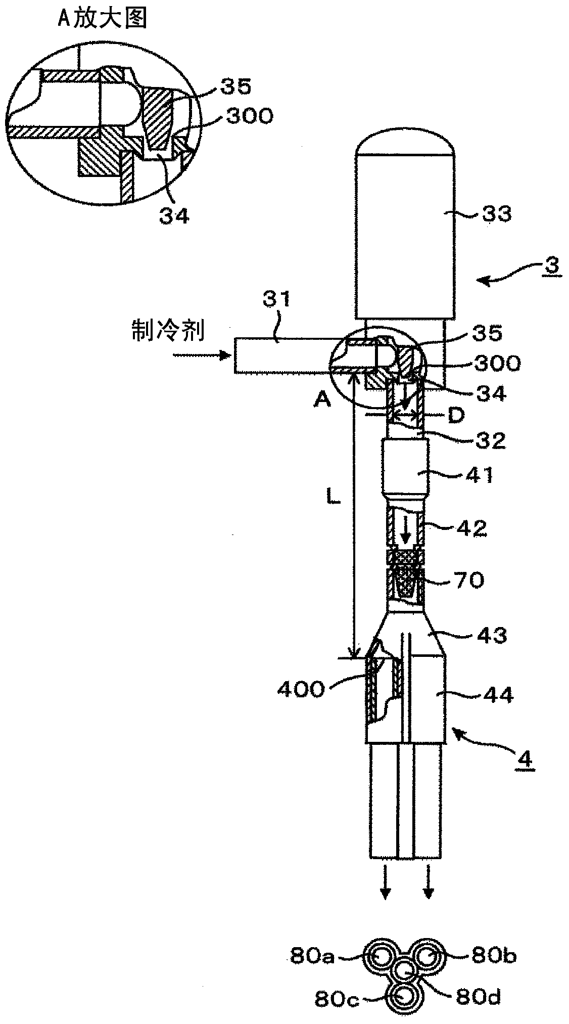
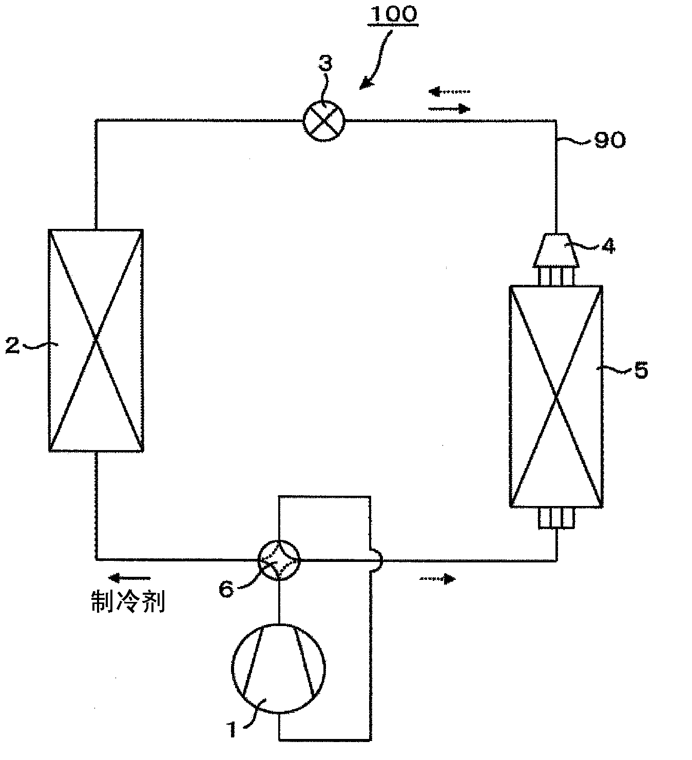
[0028] figure 2 It is an example of a configuration diagram of a refrigeration cycle device 100 according to this embodiment, for example, a room air conditioner. Here, reference numeral 1 is a compressor, reference numeral 2 is a first heat exchanger, reference numeral 3 is an expansion valve, reference numeral 4 is a refrigerant flow divider, and reference numeral 5 is a second heat exchanger , Reference numeral 6 is a four-way valve. The above-mentioned essential devices are connected by refrigerant piping to constitute the refrigeration cycle apparatus 100 .

[0029] The first heat exchanger 2 functions as a condenser, and the second heat exchanger 5 functions as an evaporator, and the refrigerant flows through compressor 1→first heat exchanger 2→expansion valve 3→refrigerant flow divider 4 →Second heat exchanger 5→The order of compressor 1 (indicated by the solid arrow) In the case of internal circulation in the refrigeration cycle device 100, the refrigerant after pas...

Embodiment 2

[0056] Figure 10 An example of a configuration diagram of a refrigeration cycle device 101 according to Embodiment 2, such as a box-type air conditioner, is shown. Here, reference numeral 1 is a compressor, reference numeral 2 is a first heat exchanger, reference numerals 3a and 3b are expansion valves, reference numerals 4a and 4b are refrigerant flow dividers, and reference numeral 5 is a second heat exchanger. In the second heat exchanger, reference numeral 6 is a four-way valve, and reference numeral 91 is a connecting pipe. Wherein, both the first heat exchanger 2 and the second heat exchanger 5 have a multi-channel structure.

[0057] When the first heat exchanger 2 functions as a condenser and the second heat exchanger 5 functions as an evaporator, as indicated by the solid line arrow in the figure, the flow is split through the first heat exchanger 2 The liquid refrigerant joined in the tank 4a passes through the expansion valve 3a and the connection pipe 91, is dec...


PUM


Abstract

The objective of the present invention is to achieve an excellent flow division characteristic under a wide range of usage conditions, without being influenced by the installation position of a refrigerant flow divider, or by manufacturing variations, or the like. This refrigeration cycle device is equipped with: a compressor that compresses a refrigerant; a condenser that condenses the refrigerant compressed by the compressor; an expansion valve (3) that decompresses the refrigerant condensed by the condenser; a flow divider (4) that is constructed separately from the expansion valve (3), and that divides the flow of the refrigerant decompressed by the expansion valve (3) into multiple flow paths formed in the interior of the flow divider; and an evaporator that vaporizes the refrigerant that has been divided by the flow divider (4). The expansion valve (3) and the flow divider (4) are arranged so as to satisfy the equations L / D <= 1.2 G0.36 and L / D >= 1.5, where L [m] is the distance from the throttle region (300) of the expansion valve (3) to the branching region (400) of the flow divider (4), D [m] is the inner diameter of a second connecting tube (32) of the expansion valve (3), and G [kg / (m2s)] is the mass velocity of the refrigerant flowing in the second connecting tube (32) of the expansion valve.

Description

technical field [0001] The present invention relates to a refrigeration cycle device provided with an expansion valve and a refrigerant flow divider. Background technique [0002] As the background art in this technical field, there is Japanese Unexamined Patent Application Publication No. 2009-24937 (Patent Document 1). An object of this prior art is to provide a refrigerant distribution chamber-integrated expansion valve in which an expansion valve and a refrigerant flow distributor are integrated, and which can easily cope with different numbers of passages. [0003] The publication describes the following content: "The valve main body is composed of a valve chamber part and a distribution chamber part. The valve chamber part uses the inside of the housing as the valve chamber, and uses the partition wall separating the valve chamber and the refrigerant distribution chamber as the bottom wall. In this The casing is formed with the inlet port that accommodates the throttl...

Claims


Application Information

Patent Timeline
Patent Type & Authority Applications(China)
IPC IPC(8): F25B41/00
CPCF25B39/028F25B41/062F25B2500/01F25B41/31
Inventor 薛隽远藤和广坪江宏明横关敦彦
Owner HITACHI JOHNSON CONTROLS AIR CONDITIONING INC
Why Eureka
Try Eureka