Optical imaging device

A technology of optical imaging and optical components, applied in optics, optical components, instruments, etc., can solve problems such as traffic accidents

Inactive Publication Date: 2014-11-12
SITRONIX TECH CORP
View PDF9 Cites 8 Cited by
  • Summary
  • Abstract
  • Description
  • Claims
  • Application Information

AI Technical Summary

Problems solved by technology

During driving, users mostly focus on the road conditions directly ahead. When users want to watch the images displayed on the head-up display during driving, users need to move their eyes to the front of the instrument panel seat or the windshield on the right front , causing the focal length of the user's eyes to change constantly, and the user's attention cannot always be focused on the road ahead, which may easily lead to traffic accidents

Method used


Image

  • Optical imaging device
  • Optical imaging device
  • Optical imaging device

Examples


Embodiment Construction

[0106] In order to make the structural features of the present invention and the achieved effects have a further understanding and recognition, preferred embodiments and detailed descriptions are specially used, which are described as follows:

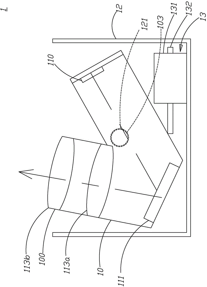
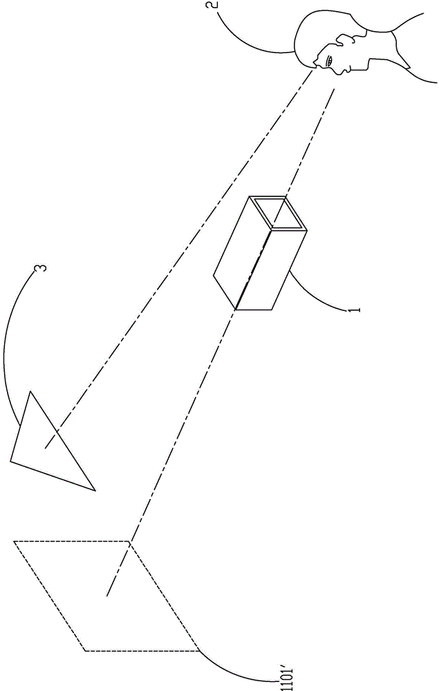
[0107] see figure 1 and figure 2 , which is a cross-sectional view and a schematic diagram of imaging of the optical imaging device of the first embodiment of the present invention; as shown in the figure, the optical imaging device 1 of this embodiment has a housing 10, a display element 110, a first optical element 113a and a second optical element 113b, the second optical element 113b is arranged in the casing 10, and is located in the opening 100, the first optical element 113a is arranged in the casing 10, and is arranged corresponding to the second optical element 113b, namely the second optical element 113b The second optical element 113b is located on the imaging path of the first optical element 113a, wherein both the first ...


PUM


Abstract

The invention provides an optical imaging device. The optical imaging device comprises a housing, a display element, a first optical element and a second optical element, the display element, the first optical element and the second optical element are disposed in the housing, the display element is located at a position far from two times of focal length of the first optical element, a display image displayed by the display element is zoomed out by the first optical element and imaged at a position within one time of focal length of the second optical element, the display image zoomed out by the first optical element is zoomed in by the second optical element so as to generate a display image which is visually zoomed in and equivalently located in the distance, so that a user can view the display image which is zoomed in and equivalently located in the distance through the optical imaging device. The optical imaging device according to the invention uses the first optical element and the second optical element, the whole optical imaging path from the display element to the second optical element is shortened, and the size of the optical imaging device is reduced.

Description

technical field [0001] The present invention relates to an imaging device, in particular to an optical imaging device. Background technique [0002] Various display devices used in vehicles have been successively developed, such as driving recorders, satellite navigation, head up displays (head up displays, HUDs), among which head up displays have been widely used. However, taking the head-up display as an example, the displayed images are mostly projected on the windshield at the front left or right front of the dashboard seat. During driving, users mostly focus on the road conditions directly ahead. When users want to watch the images displayed on the head-up display during driving, users need to move their eyes to the front of the instrument panel seat or the windshield on the right front , causing the focal length of the user's eyes to change constantly, the user's attention cannot always be concentrated on the road conditions directly ahead, which easily leads to the o...

Claims


Application Information

Patent Timeline
Patent Type & Authority Applications(China)
IPC IPC(8): G02B27/01
CPCG02B27/01G02B27/0101G02B2027/0112G02B2027/0118G02B2027/0127G02B2027/0154
Inventor 熊全宾何羽立
Owner SITRONIX TECH CORP
Why Eureka
Try Eureka