
A local annealing equipment for fasteners

A local annealing and fastener technology, applied in heat treatment equipment, furnaces, heat treatment furnaces, etc., can solve the problems of inconsistent annealing temperature, low workpiece pass rate, difficulty in ensuring installation consistency, etc., to achieve width consistency and improve processing Qualification rate and the effect of reducing input costs

Active Publication Date: 2016-03-30
AEROSPACE PRECISION PROD INC LTD
View PDF9 Cites 0 Cited by
  • Summary
  • Abstract
  • Description
  • Claims
  • Application Information

AI Technical Summary

Problems solved by technology

In the method of using traditional tooling to connect the workpiece to the motor spindle, and then put it into the coil to rotate and heat, the coaxiality and concentricity of the workpiece, the motor spindle and the coil axis will be poor; because the fasteners are generally small , when rotating and heating in the coil, the concentricity error is relatively large, and the trajectory of the workpiece is not cylindrical, which will cause one side of the rod of the fastener to always be closer to the coil, while the other side is farther away. The annealing temperature is always inconsistent; there is no shielding measure for the part of the workpiece that does not need to be annealed during induction annealing, the annealing width cannot be controlled, and manual clamping and processing will make it difficult to ensure the consistency of installation
[0005] At the same time, in the existing annealing equipment, the rigid transmission spindle is basically used. During the processing process, due to the deviation of the coaxiality, the workpiece will swing in a conical shape, which will cause severe friction between the workpiece and the positioning tool, and the long-term The friction will scratch the surface of the product, and in the face of the above situation, using the traditional universal coupling flexible transmission scheme, although the rigidity problem in the middle part can be solved, but the end of the transmission shaft is still a rigid bearing, so it is still not fundamentally Solve the friction problem during transmission
[0006] All of the above reasons will lead to large fluctuations in product performance, which will affect the use of the product, and the qualified rate of the produced workpiece will be low, which will increase the production cost.

Method used


Image

  • A local annealing equipment for fasteners
  • A local annealing equipment for fasteners
  • A local annealing equipment for fasteners

Examples


Embodiment Construction

[0054] Specific embodiments of the present invention will be described in detail below in conjunction with the accompanying drawings.

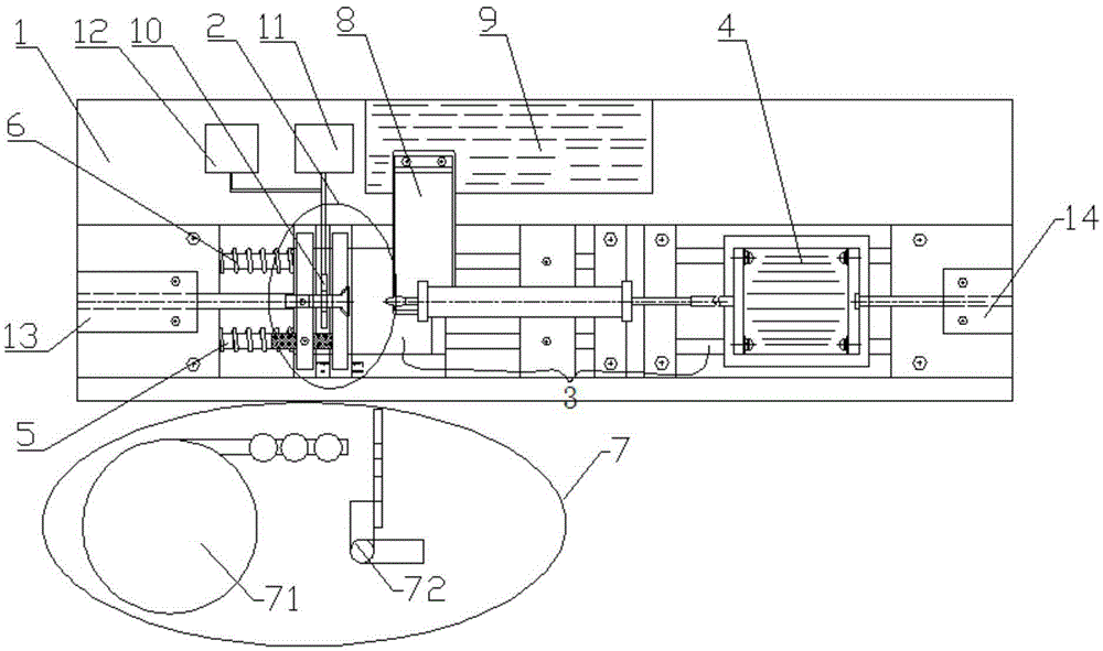
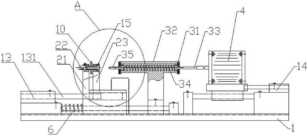
[0055] like Figure 1-4 As shown, a local annealing device for fasteners includes a positioning mechanism 2 located on a workbench 1, a flexible transmission mechanism 3, an automatic feeding mechanism 7 and a heating mechanism for heating fasteners.

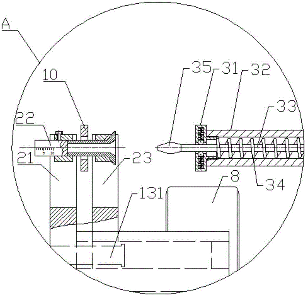
[0056] like Figure 3-9 As shown, the positioning mechanism 2 includes a fixed tool 21, a limit tool 16, a movable tool 23 slidingly fitted with the fixed tool 21, an upper measuring tool 22 and a lower measuring tool 24, and the movable tool 23 is provided with a support A positioning hole 231, the fixed tooling 21 is provided with a measurement positioning hole 211 corresponding to the supporting positioning hole 231;

[0057]Both the fixed tooling 21 and the movable tooling 23 are made of metal, which can shield the magnetic field of the heating coil 10, thereby protecting the unexposed fas...


PUM


Abstract

The invention provides local annealing equipment of a fastener. The local annealing equipment comprises a positioning mechanism, a flexible transmission mechanism and a heating mechanism for heating the fastener. The positioning mechanism comprises a fixed tool, a movable tool in sliding fit with the fixed tool and an upper measuring tool. A bearing positioning hole is formed in the movable tool, a measuring positioning hole formed corresponding to the bearing positioning hole is formed in the fixed tool, and the upper measuring tool is arranged in the measuring positioning hole. The flexible transmission mechanism comprises a flexible shaft, a hollow sleeve and a flexible bearing component. The flexible shaft penetrates through an inner cavity of the hollow sleeve, the end face of the hollow sleeve is connected with the flexible bearing component, the flexible bearing component bears the flexible shaft, and the central axis of the flexible shaft is collinear with the central axis of the measuring positioning hole and the central axis of the bearing positioning hole. The local annealing equipment is high in automation degree, can precisely control the annealing starting position and the annealing width and does not damage a workpiece, and therefore the production yield is improved.

Description

technical field [0001] The invention belongs to the processing field of fasteners, in particular to local annealing equipment for fasteners. Background technique [0002] In some specific fastener processing, local annealing treatment is required to make it locally deformed during installation to achieve the purpose of fastening. [0003] However, for fasteners that require partial annealing, in order to ensure the consistency of installation performance and service performance, there are special requirements for the starting position of partial annealing of the shank of the fastener, as well as the annealing width and dimensional consistency. This requires that the annealing position and annealing width of the stem must be strictly controlled within a certain range, so the annealing method of the stem is particularly important. [0004] At present, induction heating coils are mainly used for partial annealing of the stem. In the method of using traditional tooling to conn...

Claims


Application Information

Patent Timeline
Patent Type & Authority Patents(China)
IPC IPC(8): C21D9/00C21D1/26
Inventor 桂林景胡隆伟刘如刚刘智昂柳阳阳齐跃
Owner AEROSPACE PRECISION PROD INC LTD
Learn More