A method for achieving monitoring camera lens

A realization method and lens technology, applied to camera bodies, color TV parts, TV system parts, etc., can solve problems such as limited functions, and achieve the effect of ingenious design, novel structure and strong flexibility

Inactive Publication Date: 2014-11-19
CENTRAL SOUTH UNIVERSITY OF FORESTRY AND TECHNOLOGY
View PDF4 Cites 1 Cited by
  • Summary
  • Abstract
  • Description
  • Claims
  • Application Information

AI Technical Summary

Problems solved by technology

[0002] In the field of video surveillance, conventional lenses are generally used to obtain images, but the existing optical lenses have only one light outlet, which has limited functions and a...

Method used


Image

  • A method for achieving monitoring camera lens
  • A method for achieving monitoring camera lens
  • A method for achieving monitoring camera lens

Examples


Embodiment 1

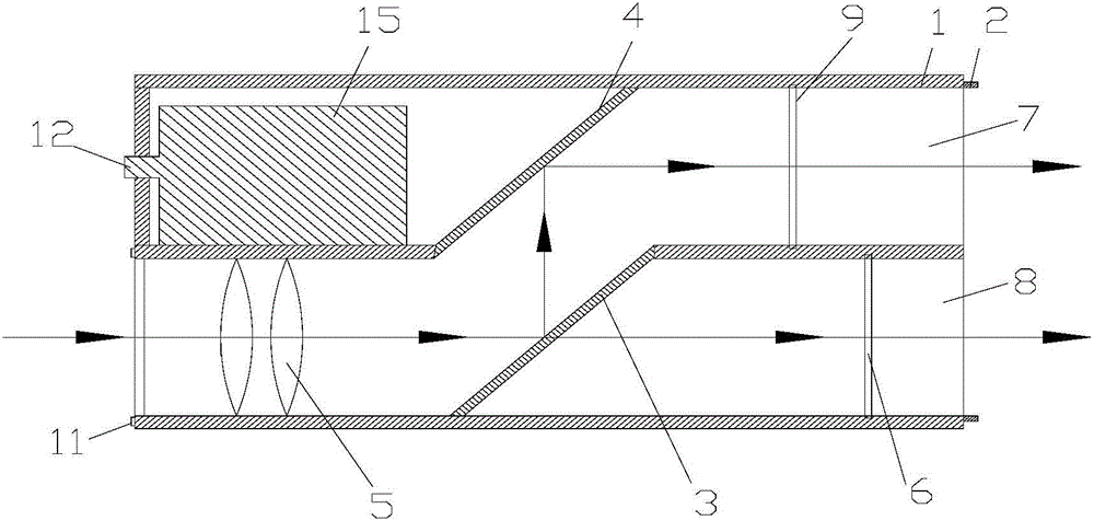
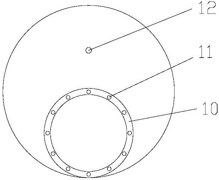
[0033] Such as Figure 1-3 As shown, a method for realizing a monitoring lens is provided with an inner cylinder (10), a semi-transparent mirror (3), a mirror (4), an infrared induction identification system (15) in the outer cylinder (1) of the lens. ), a lens group (5), an infrared cut filter (6) and a visible light cut filter (9); the rear end of the outer cylinder is provided with a lens bayonet (2);

[0034] The positional relationship of each component is as follows: the axis of the inner cylinder is parallel to the axis of the outer cylinder;

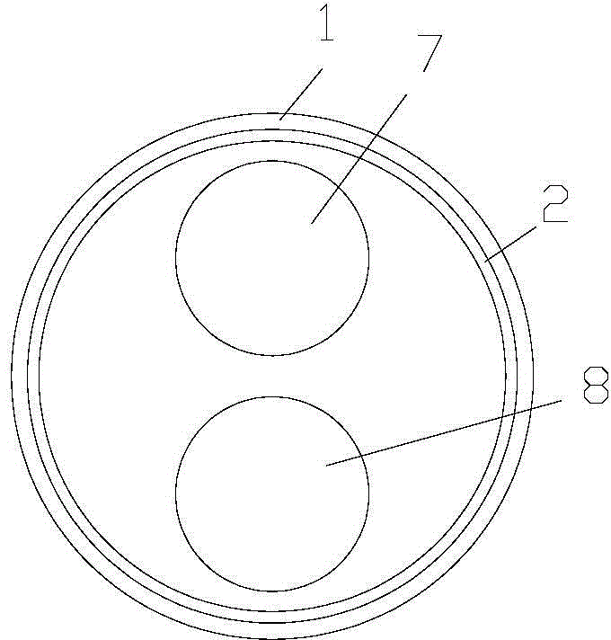
[0035] The front opening of the inner cylinder is a light inlet, and the light inlet is located on the front surface of the outer cylinder, and the rear end of the outer cylinder has two light outlets, the two light outlets are the first light outlet (7) and the second light outlet port (8); the lens group (5) is arranged in the inner cylinder in a manner perpendicular to the axis of the inner cylinder; the infrared cut-off filt...


PUM


Abstract

The present invention discloses a method for achieving a monitoring camera lens, wherein an internal barrel (10), a translucence retroreflector (3), a reflector (4), an infrared induction and recognition system (15), an optical lens group (5), an IR cut-off filter (6) and a visible light cut-off filter (9) are disposed inside an external barrel (1) of the camera lens; and a camera lens bayonet (2) is disposed on a rear end of the external barrel to form the following two light paths: (1) after entering from a light entering opening, external light successively penetrates the camera lens group, the translucence retroreflector and the IR cut-off filter, and finally emits from a second light outlet to form a transmission light path; and (2) after entering from the light entering opening, the external light first penetrates the camera lens group, then is reflected by the translucence retroreflector and the reflector, penetrates the visible light cut-off filter, and finally emits from a first light outlet to form the transmission light path. The achieving method of the monitoring camera lens is novel and ingenious, which is especially suitable for a monitoring occasion.

Description

technical field [0001] The invention relates to a method for realizing a monitoring lens. Background technique [0002] In the field of video surveillance, conventional lenses are generally used to obtain images, but the existing optical lenses have only one light outlet, which has limited functions and are more suitable for ordinary occasions. Therefore, it is necessary to design a new type of optical lens with a compound lens structure. The lens is specially used in the field of video surveillance. Contents of the invention [0003] The technical problem to be solved by the present invention is to provide a method for realizing a monitoring lens, which is novel and ingenious, and is especially suitable for monitoring occasions. [0004] The technical solution of the invention is as follows: [0005] A method for realizing a monitoring lens, in which an inner cylinder (10), a semi-transparent mirror (3), a reflection mirror (4), an infrared induction identification syst...

Claims


Application Information

Patent Timeline
IPC IPC(8): H04N5/225G03B17/17G03B17/12G03B15/05
Inventor 贺超英
Owner CENTRAL SOUTH UNIVERSITY OF FORESTRY AND TECHNOLOGY
Why Eureka
Try Eureka