Optical cable testing device

A test device and optical cable technology, which is applied in the direction of measuring devices, instruments, scientific instruments, etc., can solve the problems of not enough to reflect the advantages of maximizing the utilization of resources, troublesome clamping operation of the tested optical cable, and many action transmission links, so as to reduce clamping The strength of the loading operation, fast and reliable clamping, and the effect of reducing the action transmission link

Active Publication Date: 2014-11-26
常熟市环境试验设备有限公司
View PDF8 Cites 12 Cited by
  • Summary
  • Abstract
  • Description
  • Claims
  • Application Information

AI Technical Summary

Problems solved by technology

It can be seen that although this patent solution can embody the technical effects recorded in paragraphs 0013 to 0014 of its description, objectively there are the following shortcomings: First, because there are many action transmission links, it is not conducive to saving the cost of the motor as the power transmission mechanism. energy consumption; second, due to the need to use racks (patented toothed sliders) and gears, not only the structure is complex, but also the racks and gears are easy to wear and affect the test results; In addition to the guide device and the pressing device, the clamping device also needs to use a winding wheel designed to tension the optical cable under test (for details, please refer to paragraphs 0023 to 0025 of the specification of the patent), so in practice During the test process, the clamping operation of the tested optical cable is more troublesome; fourth, because it can only meet the requirements of the optical cable winding test, it cannot cope with other test items such as the aforementioned torsion test and wire torsion test, which is not enough to reflect the need for resources. maximize the advantages of

Method used


Image

  • Optical cable testing device
  • Optical cable testing device
  • Optical cable testing device

Examples


Embodiment Construction

[0024] In order to enable the examiners of the patent office, especially the public, to understand the technical essence and beneficial effects of the present invention more clearly, the applicant will describe in detail the following in the form of examples, but none of the descriptions to the examples is an explanation of the solutions of the present invention. Any equivalent transformation made according to the concept of the present invention which is merely formal but not substantive shall be regarded as the scope of the technical solution of the present invention.

[0025] In the following descriptions, all concepts involving up, down, left, right, front and rear directionality (or orientation) are for the position state of the picture being described, and the purpose is to facilitate the public Therefore, it cannot be understood as a special limitation on the technical solution provided by the present invention.

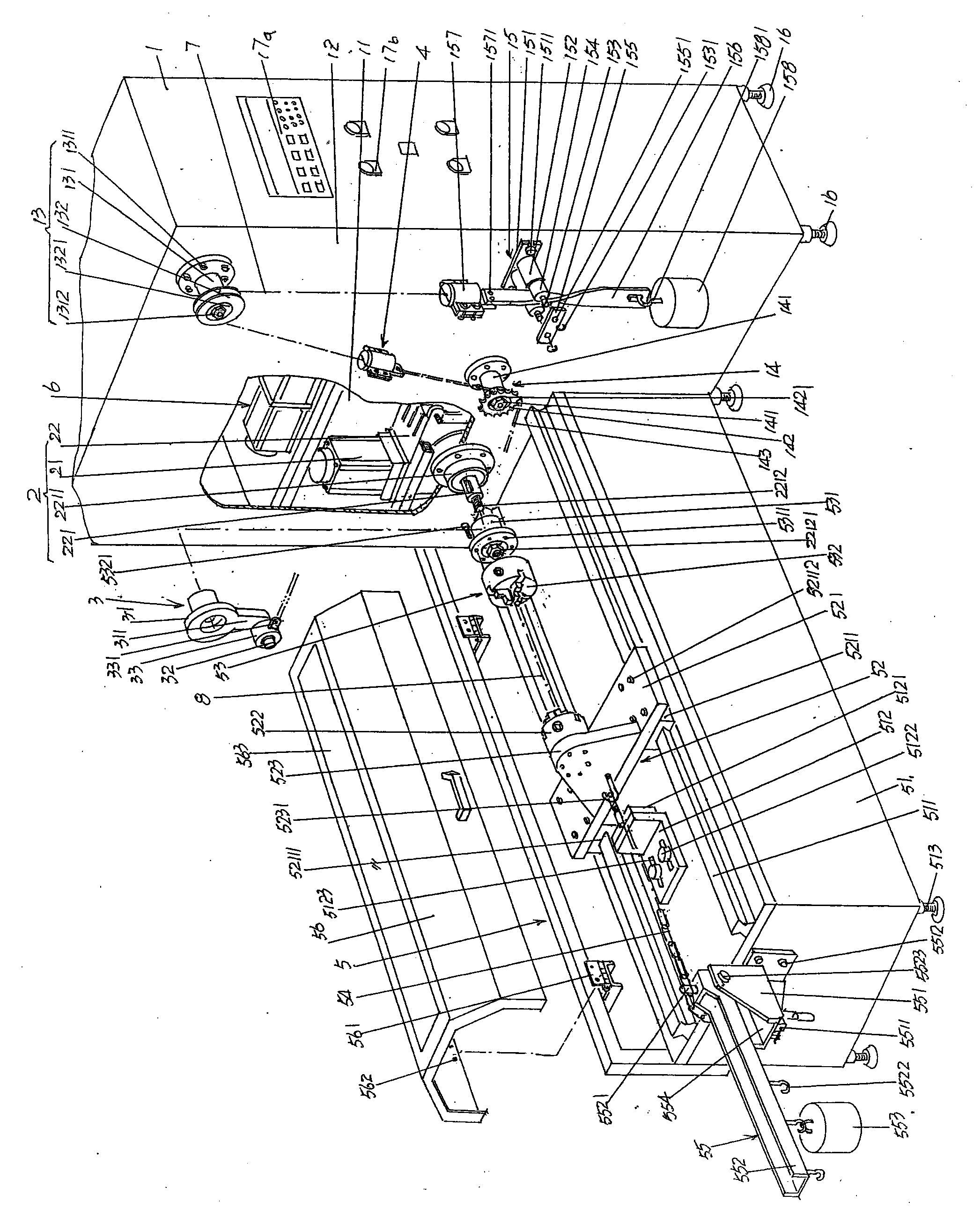
[0026] See figure 1 , a cabinet body 1 with a rectangul...


PUM


Abstract

The invention discloses an optical cable testing device, belonging to the technical field of optical cable testing equipment. The optical cable testing device comprises a cabinet body, a power transmission mechanism, a cam mechanism, a steel wire twisting testing device and an optical cable winding testing device, wherein the cabinet body is provided with a cabinet body chamber; an optical cable transition guide mechanism, a traction transmission mechanism and an optical cable twisting mechanism are arranged on the cabinet body; the optical cable transition guide mechanism is positioned at the upper part of a left cabinet wall; the optical cable twisting mechanism is positioned at the lower part of the left cabinet wall; the traction transmission mechanism corresponds to the rear side of the optical cable twisting mechanism; the power transmission mechanism is arranged inside the cabinet body chamber; the cam mechanism is connected with the power transmission mechanism and is connected with the traction transmission mechanism; the steel wire twisting testing device is arranged on one side opposite to the cabinet body chamber corresponding to the left cabinet wall of the cabinet body and is connected with the power transmission mechanism; the optical cable winding testing device is arranged inside the cabinet body chamber. The action transmission procedures are reduced, the structure is simplified, the testing effect of an optical cable is ensured, the optical cable is rapidly and reliably clamped, the working intensity is alleviated, basis is provided for setting of the optical cable winding testing device, power for the steel wire twisting testing device can be converted, and the optical cable testing device is applicable to different testing items.

Description

technical field [0001] The invention belongs to the technical field of optical cable test equipment, and in particular relates to an optical cable test device, which is used for torsion test and winding test of optical cable and steel wire torsion test for optical cable. Background technique [0002] Optical cable test is an indispensable link for optical cable product quality supervision and inspection agencies and even manufacturers to grasp the quality of optical cables. The equipment that optical cable tests rely on is the aforementioned optical cable test device. The optical cable test device performs torsion tests and winding tests on optical cables. Even the torsion test is performed on the steel wire (usually galvanized steel wire) used in the optical cable, so that after the test, the optical cable can be used for subsequent instruments to measure properties such as loss, reflection, and light transmission, etc. [0003] As known in the industry, in recent years, th...

Claims


Application Information

Patent Timeline
Patent Type & Authority Applications(China)
IPC IPC(8): G01N3/00G01N3/04
Inventor 陈国华
Owner 常熟市环境试验设备有限公司
Why Eureka
Try Eureka