Aligning tool, aligning method, fiber inserting core assembly, and fiber connector

A fiber optic connector and fiber optic ferrule technology, which is applied in the coupling of optical waveguides, etc., can solve the problems of low multimode ferrule single-mode fiber optic connector ferrule, high cost of single-mode connectors, and high requirements for related dimensions. , to achieve the effects of low cost, improved performance, random intermatability, and low loss

Inactive Publication Date: 2014-12-03
TYCO ELECTRONICS (SHANGHAI) CO LTD
View PDF6 Cites 16 Cited by
  • Summary
  • Abstract
  • Description
  • Claims
  • Application Information

AI Technical Summary

Problems solved by technology

The single-mode / multi-mode ferrules used in fiber optic connectors seem to have the same appearance and structure, but the single-mode ferrules have high requirements on the relevant dimensions of the ferrules, especially the size of the fiber through holes of the ferrules and their alignment. The position accuracy between the guide holes is extremely high (usually within 3 microns, in order to meet the ultra-low insertion loss of the butt connection, the accuracy must even be controlled at the sub-micron level). The most direct result of the high precision requirement is that single The high cost / price of the ferrule leads to the high cost of single-mode connectors, especially for ultra-low loss multi-core fiber optic ferrule connectors. The cost of single-mode and multi-mode ferrules is almost several times different
[0015] As mentioned above, according to the prior art, low-precision multimode ferrules cannot be used to manufacture high-precision single-mode fiber optic connector ferrules

Method used


Image

  • Aligning tool, aligning method, fiber inserting core assembly, and fiber connector
  • Aligning tool, aligning method, fiber inserting core assembly, and fiber connector
  • Aligning tool, aligning method, fiber inserting core assembly, and fiber connector

Examples


Embodiment Construction

[0079] The technical solutions of the present invention will be further specifically described below through the embodiments and in conjunction with the accompanying drawings. In the specification, the same or similar reference numerals designate the same or similar components. The following description of the embodiments of the present invention with reference to the accompanying drawings is intended to explain the general inventive concept of the present invention, but should not be construed as a limitation of the present invention.

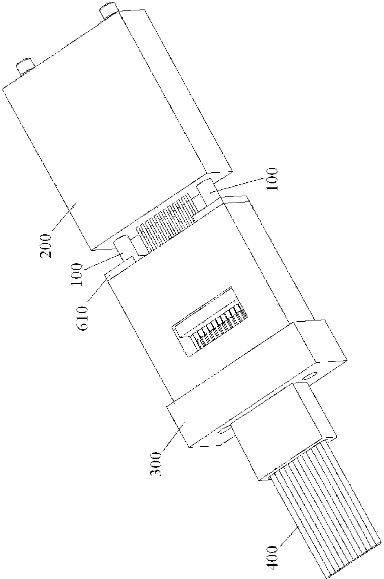
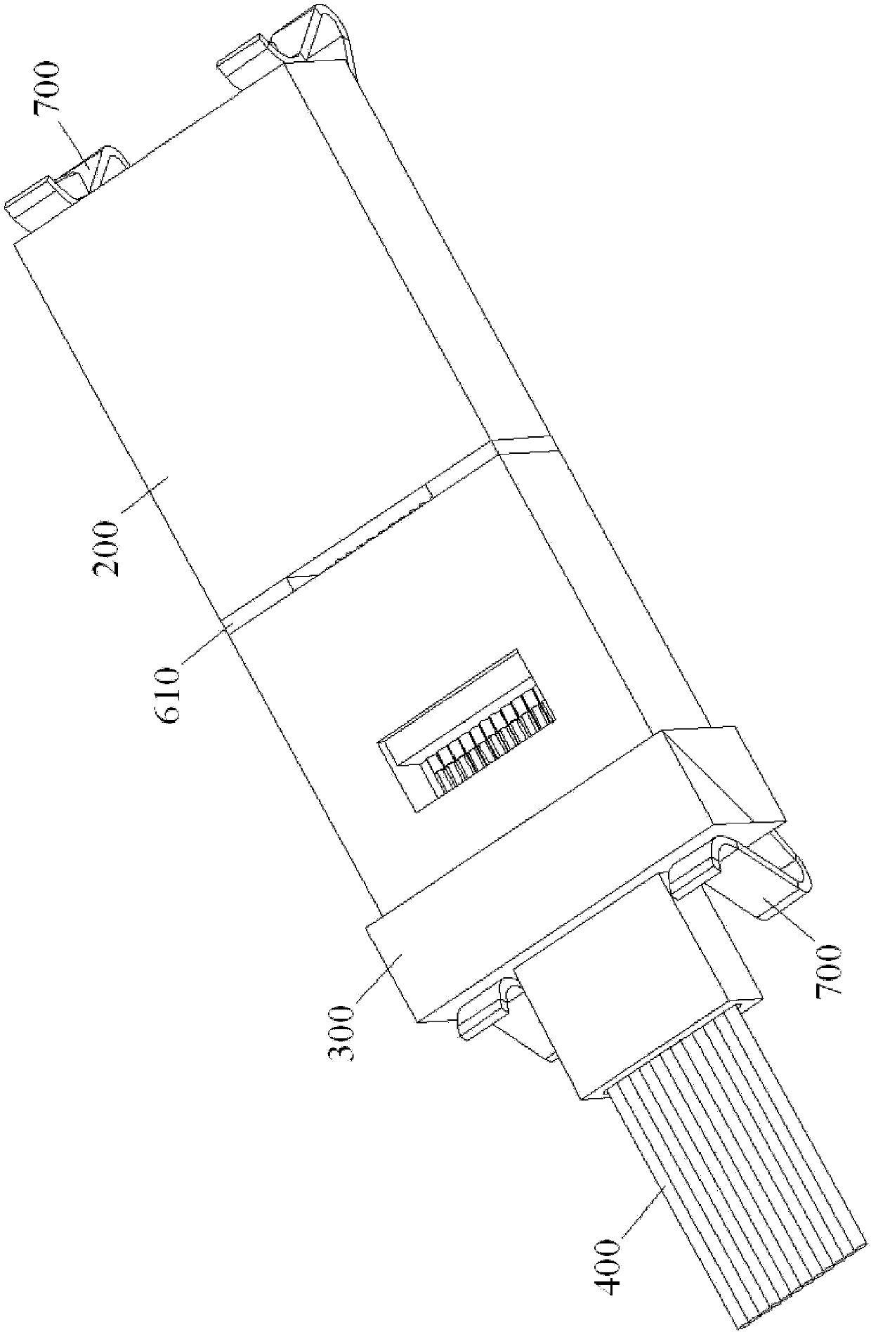
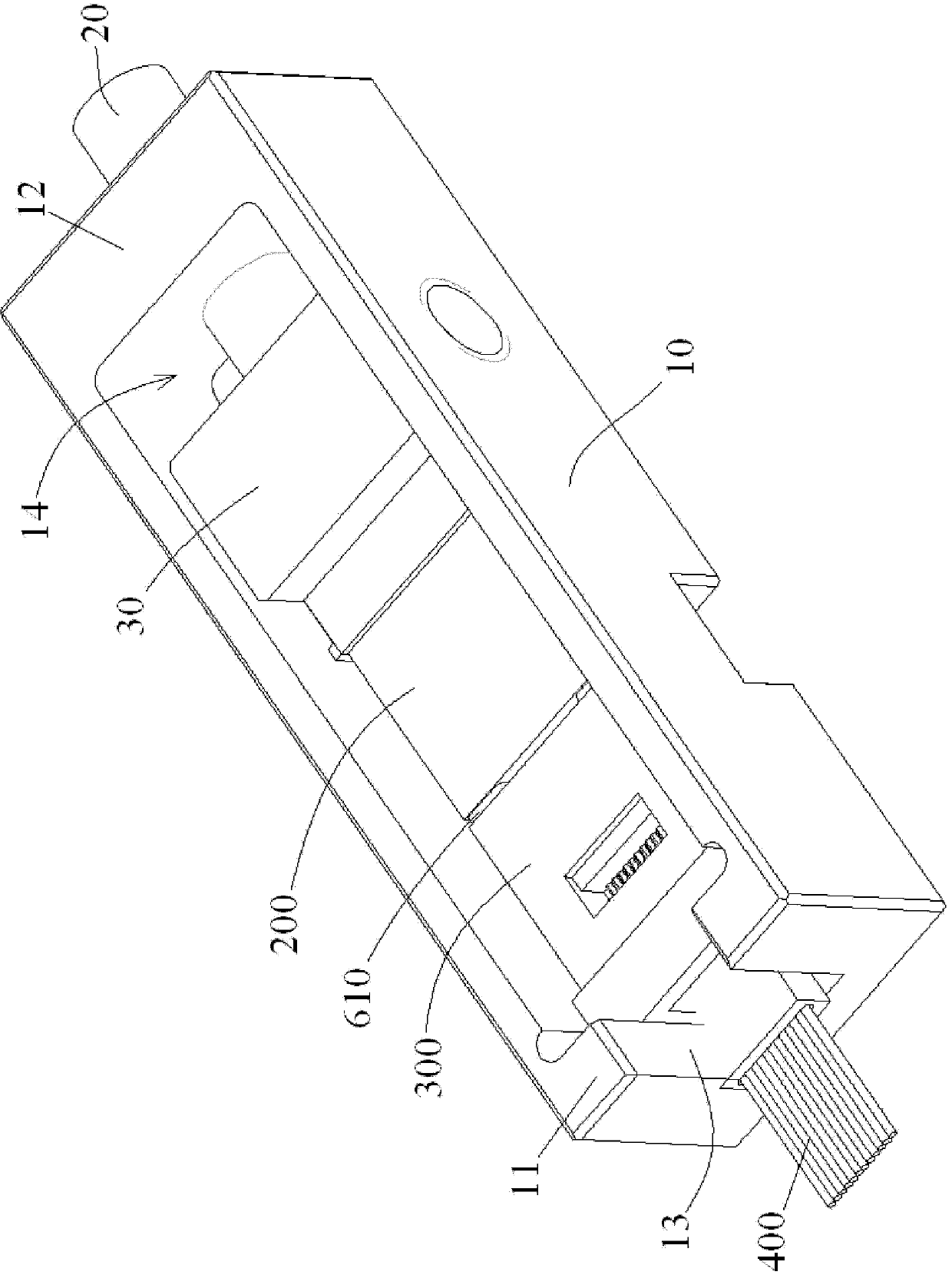
[0080] figure 1 It is a schematic diagram of an alignment tool for manufacturing a holey fiber ferrule 300 according to the first exemplary embodiment of the present invention. figure 2 for figure 1 Schematic of the alignment tool shown, showing the alignment tool's clamps and spacing controls. image 3 for figure 1 and figure 2 A perspective schematic of the alignment tool shown in .

[0081] like figure 1 , figure 2 and image 3 ...


PUM


Abstract

The invention discloses an aligning tool used for calibrating the positions of fibers in fiber through holes of a multi-hole fiber inserting core. The aligning tool comprises a high-precision alignment guiding element and a high-precision fiber position aligning element. The fiber inserting core is butted with the aligning tool through the high-precision alignment guiding element. Multiple fibers pass through the multiple fiber through holes of the fiber inserting core and are inserted into the multiple calibrating holes of the high-precision fiber position aligning element in order that the positional precision of the fibers in the fiber through holes of the fiber inserting core reaches the positional precision of the fibers in the calibrating holes of the high-precision fiber position aligning element. Therefore, a high-precision fiber connector is produced by a low-precision fiber inserting core and production cost is reduced. The invention also discloses an aligning method and a high-precision fiber connector produced by using the aligning tool and the aligning method and provided with precision equal to or more than that of a single-mode fiber connector.

Description

technical field [0001] The invention belongs to the field of optical fiber connectors, and the invention relates to a method for calibrating optical fibers (including conventional single-core optical fibers, multi-core single fibers, bundled multi-fibers or multi-fiber bundles, and the "fiber" mentioned below in this document has the same meaning as here Alignment tool and alignment method indicating the position of the same (included) in the optical fiber through-hole of a multi-core optical fiber ferrule (having a hole, accommodating a plurality of optical fibers) and manufacturing by such alignment tool and alignment method Fiber ferrule components and fiber optic connectors. Specifically, the present invention proposes a low-precision ferrule (with larger fiber through-hole diameter and eccentricity, such as a multimode ferrule or a lower specification than a multimode ferrule) to manufacture low-cost, high-efficiency The new process technology of single-mode fiber optic ...

Claims


Application Information

Patent Timeline
Patent Type & Authority Applications(China)
IPC IPC(8): G02B6/38G02B6/36
Inventor 童朝阳刘蕾林麟
Owner TYCO ELECTRONICS (SHANGHAI) CO LTD
Why Eureka
Try Eureka