Lamp

A technology for lamps and lamp sockets, which is applied to lighting devices, electric light sources, components of lighting devices, etc., can solve the problems of single lighting direction, long time consumption, light source damage, etc. changing effect

Active Publication Date: 2014-12-17
SHENZHEN OCEANS KING LIGHTING ENG CO LTD +1
View PDF6 Cites 0 Cited by
  • Summary
  • Abstract
  • Description
  • Claims
  • Application Information

AI Technical Summary

Problems solved by technology

This method in the prior art has the following defects: 1. The light source is generally a fragile product, and a new light source for replacement needs a special storage space, so storing the light source will bring a lot of trouble
2. In some harsh environments, the frequency of damage to the light source is high, and the lamp is installed at a high place and is not easy to replace. If the conventional method is used, it will bring great trouble to maintenance. When replacing, the light source should be carried for high work, increasing the difficulty of maintenance
3. In some occasions where the lighting cannot be interrupted for a long time, if the light source is damaged, it will take a long time to go to the warehouse to get the light source, find tools, and then replace the light source, which will cause inconvenience to the user
4. The light source of lamps and lanterns in the prior art is generally fixed in the lamp housing, and cannot be moved or rotated in the lamp housing. The single lighting direction can only be illuminated according to the direction of design, and it is impossible to achieve the same lighting angle and angle by changing the position of the light source. direction adjustment

Method used


Image

  • Lamp
  • Lamp
  • Lamp

Examples


Embodiment Construction

[0027] In order to further illustrate the principle and structure of the present invention, preferred embodiments of the present invention will now be described in detail with reference to the accompanying drawings.

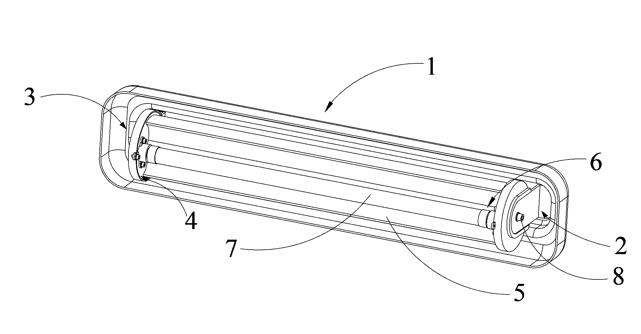
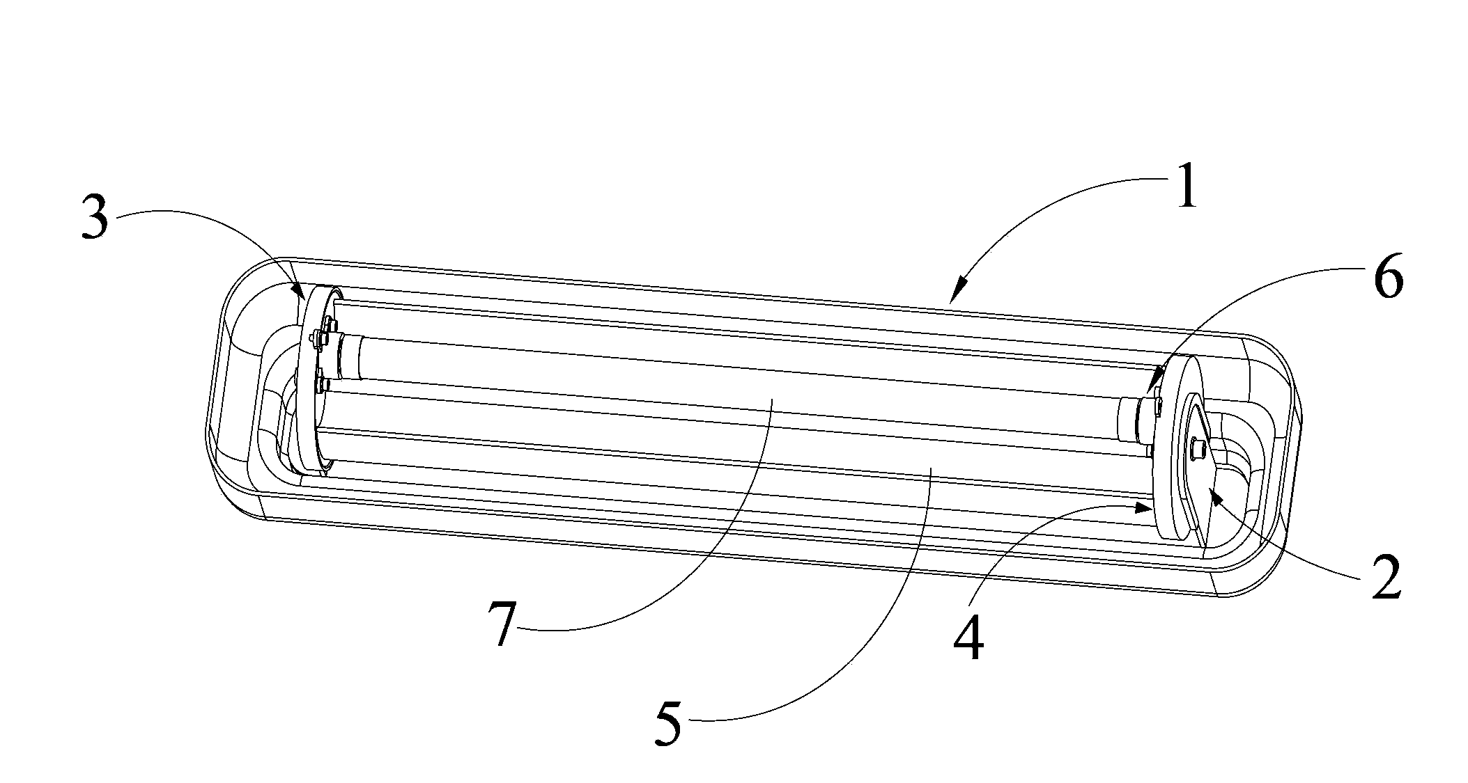
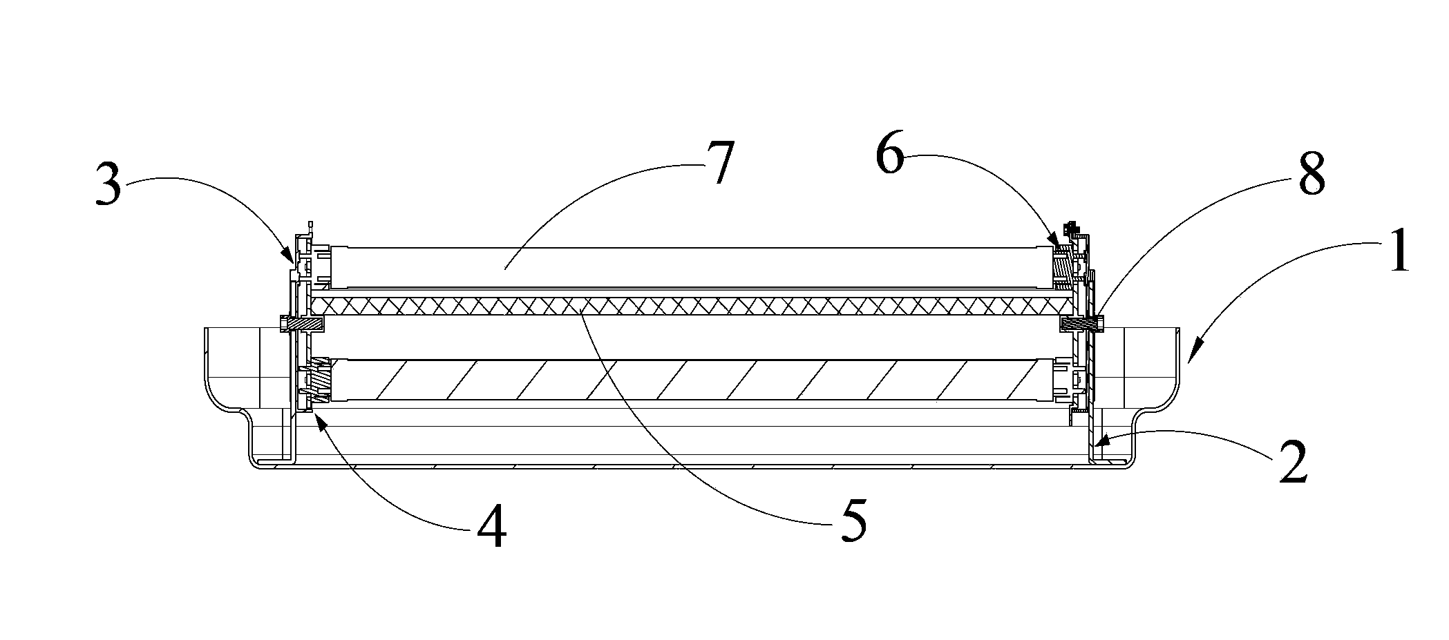
[0028] see figure 1 , The present invention provides a lamp, which includes: a lamp housing 1, two mounting plates 2, two contact plates 3, two rotating plates 4, a reflector 5, four lamp holders 6 and two lamp tubes 7.

[0029] Lamp housing 1. In this embodiment, the lamp housing 1 includes a lamp housing base 11 and a lamp housing extension 12 formed by flanging the lamp housing base 11. The lamp housing extension 12 and the lamp housing base 11 form an accommodating portion , the mounting plate 2 is fixedly connected to the lamp housing base 11 of the lamp housing 1, and the accommodating part is used to accommodate other components of the lamp. The purpose of adopting such a structure is to protect other components in the lamp through the wrapping of the lam...


PUM


Abstract

The invention discloses a lamp. The lamp comprises a lamp housing, two installation plates, two contact discs, two rotary discs, a reflector, four lamp holders, two lamp tubes and a fixing mechanism, wherein three pairs of electrode holders are arranged on the first surface of each contact disc, the two contact discs are respectively fixedly connected with the corresponding installation plate, the two rotary discs are respectively connected with the corresponding contact disc in a rotary mode, the reflector is formed by connecting four reflecting surfaces in an end-to-end mode, the two ends of the reflector are fixedly connected with the two rotary discs, the four lamp holders are fixed to the rotary discs respectively and are divided into two pairs, the two lamp holders of each pair are oppositely arranged on and fixed to the two rotary discs respectively, the two ends of each lamp tube are connected with the corresponding pair of lamp holders, when the rotary discs rotate, the pair of lamp holders which are originally in contact with the electrode holders on the contact discs are disconnected with the corresponding electrode holders, and contact pins of the other group of lamp holders are in contact with the electrode holders on the contact discs. According to the lamp, the lamp tubes are both installed on the lamp and are driven through rotation of the rotary discs to rotate, and in this way, when the lamp tubes need to be replaced, troublesome operation of lamp tube storage and direct replacement of the lamp tubes is avoided.

Description

technical field [0001] The invention relates to a lighting appliance, in particular to a lamp. Background technique [0002] Existing lamps and lamps for ships are generally equipped with only one light source, which needs to be replaced with a new light source when the light source is damaged or its life is terminated. This method in the prior art has the following defects: 1. The light source is generally a fragile product, and a new light source for replacement needs a special storage space, so storing the light source will bring a lot of trouble. 2. In some harsh environments, the frequency of damage to the light source is high, and the lamp is installed at a high place and is not easy to replace. If the conventional method is used, it will bring great trouble to maintenance. When replacing, the light source should be carried for high It is difficult to do maintenance work. 3. In some occasions where the lighting cannot be interrupted for a long time, if the light sour...

Claims


Application Information

Patent Timeline
Patent Type & Authority Applications(China)
IPC IPC(8): F21S2/00F21V19/02
Inventor 周明杰李鹏飞
Owner SHENZHEN OCEANS KING LIGHTING ENG CO LTD
Why Eureka
Try Eureka