Common voltage compensation circuit, compensation method thereof, array substrate and display device
A common voltage and compensation circuit technology, applied to static indicators, instruments, etc., can solve problems such as abnormal gray scale display, crosstalk, and screen jitter
- Summary
- Abstract
- Description
- Claims
- Application Information
AI Technical Summary
Problems solved by technology
Method used
Image
Examples
example 1
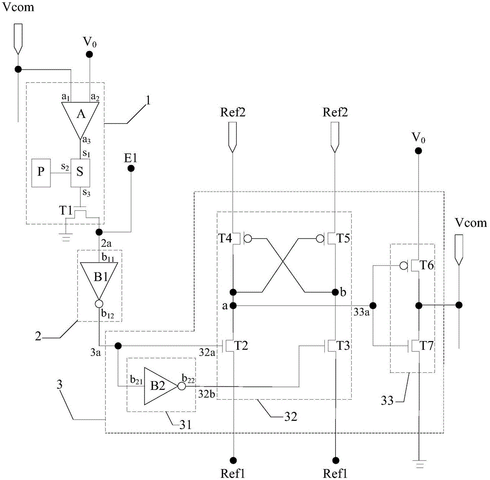
[0077] Example 1: If image 3 As shown, the control power supply P controls the sampler S to turn on, and the sampler S samples the comparison result of the common voltage and the reference voltage obtained by the comparator A:
[0078] When the difference between the common voltage and the reference voltage is greater than or equal to the preset threshold, the comparator A inputs a high-level signal to the gate of the first switching transistor T1 through the sampler S, so that the first switching transistor T1 is in a conducting state, so that the input terminal b of the first inverter B1 11 and the port E1 for inputting the first level signal is grounded; the gate of the first inverter B1 to the gate of the second switching transistor T2 and the input terminal b of the second inverter B2 21 output the second level signal, the second inverter B2 converts the second level signal into a zero-voltage signal and sends it to the gate of the third switching transistor T3, the sec...
example 2
[0080] Example 2: If Figure 4 As shown, the control power supply P controls the sampler S to turn on, and the sampler S samples the comparison result of the common voltage and the reference voltage obtained by the comparator A:
[0081] When the difference between the common voltage and the reference voltage is greater than or equal to the preset threshold, the comparator A inputs a high-level signal to the gate of the first switching transistor T1 through the sampler S, so that the first switching transistor T1 is in a conducting state, so that the input terminal b of the first inverter B1 11 and the port E1 for inputting the first level signal is grounded; the gate of the first inverter B1 to the gate of the second switching transistor T2 and the input terminal b of the second inverter B2 21 output the second level signal, the second inverter B2 converts the second level signal into a zero-voltage signal and sends it to the gate of the third switching transistor T3, the se...
example 3
[0083] Example 3: If Figure 5 As shown, the control power supply P controls the sampler S to turn on, and the sampler S samples the comparison result of the common voltage and the reference voltage obtained by the comparator A:
[0084] When the difference between the common voltage and the reference voltage is greater than or equal to the preset threshold, the comparator A inputs a high-level signal to the gate of the first switching transistor T1 through the sampler S, so that the first switching transistor T1 is in a conducting state, so that the input terminal b of the first inverter B1 11 and the port E1 for inputting the first level signal is grounded; the gate of the first inverter B1 to the gate of the second switching transistor T2 and the input terminal b of the second inverter B2 21 output the second level signal, the second inverter B2 converts the second level signal into a zero-voltage signal and sends it to the gate of the third switching transistor T3, the se...
PUM
 Abstract
Description
Claims
Application Information
 - R&D
- Intellectual Property
- Life Sciences
- Materials
- Tech Scout
- Unparalleled Data Quality
- Higher Quality Content
- 60% Fewer Hallucinations
Browse by: Latest US Patents, China's latest patents, Technical Efficacy Thesaurus, Application Domain, Technology Topic, Popular Technical Reports.
© 2025 PatSnap. All rights reserved.Legal|Privacy policy|Modern Slavery Act Transparency Statement|Sitemap|About US| Contact US: help@patsnap.com


