Wall Outlet Adapter

A technology for wall sockets and converters, applied in electrical components, coupling devices, circuits, etc., can solve problems such as poor stability, fatigue and aging of sockets

Active Publication Date: 2016-04-27
BULL GRP CO LTD
View PDF6 Cites 0 Cited by
  • Summary
  • Abstract
  • Description
  • Claims
  • Application Information

AI Technical Summary

Problems solved by technology

[0004] The first purpose of the present invention is to provide a wall socket converter that can make full use of the redundant jack groups on the wall socket to improve connection reliability, which solves the problem that the existing socket converters are used for wall sockets. Fatigue aging and poor stability of sockets in wall sockets

Method used


Image

  • Wall Outlet Adapter
  • Wall Outlet Adapter
  • Wall Outlet Adapter

Examples


Embodiment 1

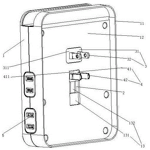
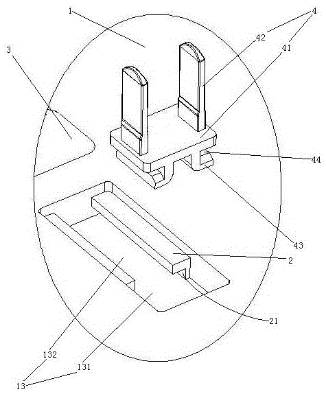
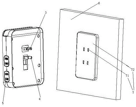
[0025] Embodiment one, see figure 1 , a wall socket converter, including an insulating shell 1, a slide rail 2, a power input plug 3 and a fixed plug 4.

[0026] The housing 1 is provided with an output port 5 . The output port 5 includes a USB interface, a socket and a DC power outlet. The back of the shell 1 is provided with a skirt 11 . The skirt 11 and the shell 1 form a cover 12 . A pit 13 is provided on the back of the shell 1 . The pit 13 is a cuboid extending in the up-down direction. The recess 13 includes a plug entry section 131 and a slide rail installation section 132 distributed in sequence.

[0027] There are two slide rails 2. The slide rail 2 extends in the vertical direction. The two slide rails 2 are respectively fixed on the left and right side walls of the slide rail installation section 132 .

[0028]The power inlet plug 3 is located in the cover 12 . The power inlet plug 3 is arranged directly on the rear side of the housing 1 . The power inlet...

Embodiment 2

[0033] Embodiment two, the difference with embodiment one is:

[0034] see Figure 4 , The sliding hook 43 is provided with a locking joint 431 and a spring 432 . The clip joint 431 is cylindrical. The clip joint 431 is rotatably connected to the end surface of the sliding hook 43 . The axis of the snap joint 431 extends in the left-right direction. The spring 432 is used to make the snap joint 431 protrude in the left-right direction. The plug entry section 131 is provided with a locking hole 14 . The clamping joint 431 is clamped in the clamping hole 14 under the action of the spring 432 , and the clamping joint 431 can rotate in the clamping hole 14 around the axis. The pit 13 is provided with a flat space 15 for fixing the plug. Each fixed socket pin 42 is respectively provided with a lead structure 8 . The lead structure 8 includes a conductive head 81 and a conductive sheet 82 . The two conductive heads 81 are provided in the two snap connectors 431 in a one-to-o...


PUM


Abstract

The invention relates to a convertor, in particular to a wall socket convertor which comprises an insulated outer shell, a power leading-in plug, a fixed plug and a plurality of output ports formed in the outer shell. The power leading-in plug is electrically connected with an electrical appliance output port and connected to the surface of the outer shell, the fixed plug comprises a fixed plug insulating seat and fixed plug pins connected to the fixed plug insulating seat, a slide rail is further arranged on the outer shell, the fixed plug insulating seat is connected to the slide rail in a sliding mode, the fixed plug and the power leading-in plug are located on the same side of the outer shell, and the extending direction of the slide rail is the same as the distribution directions of the power leading-in plug and the fixed plug. The wall socket convertor is used for improving connection reliability by fully utilizing surplus jacks in a wall socket, and the problems that when an existing socket convertor is used for a wall socket, fatigue and aging of a plug bush in the wall socket are likely to happen, and stability is poor are solved.

Description

technical field [0001] The invention relates to a converter, in particular to a wall socket converter. Background technique [0002] At present, there are many specifications and types of plugs used in electrical products. Different countries and different electrical connection needs have different specifications of plugs and sockets. There are two-core type, three-core type, US plug-in interface, and DC output plug and interface, etc. When these different plugs are in use, a converter is needed to connect the plug of the electrical appliance to the socket. A socket converter has been designed for this purpose. A socket converter is disclosed in a patent document with the Chinese patent number 2012203950888, the authorized announcement date being March 27, 2013, and the title "A New Type of Travel Socket Converter". The basic structures of existing socket converters are all as disclosed in this patent document, including an insulating shell, a power input plug and a numbe...

Claims


Application Information

Patent Timeline
Patent Type & Authority Patents(China)
IPC IPC(8): H01R31/06
Inventor 王鸿达夏绍松陆展科
Owner BULL GRP CO LTD
Why Eureka
Try Eureka