
Headlight control device

A technology for control devices and headlights, applied in signal devices, headlights, transportation and packaging, etc., can solve problems such as glare, achieve the effect of preventing glare and simplifying the composition

Inactive Publication Date: 2014-12-31
SUBARU CORP
View PDF2 Cites 10 Cited by
  • Summary
  • Abstract
  • Description
  • Claims
  • Application Information

AI Technical Summary

Problems solved by technology

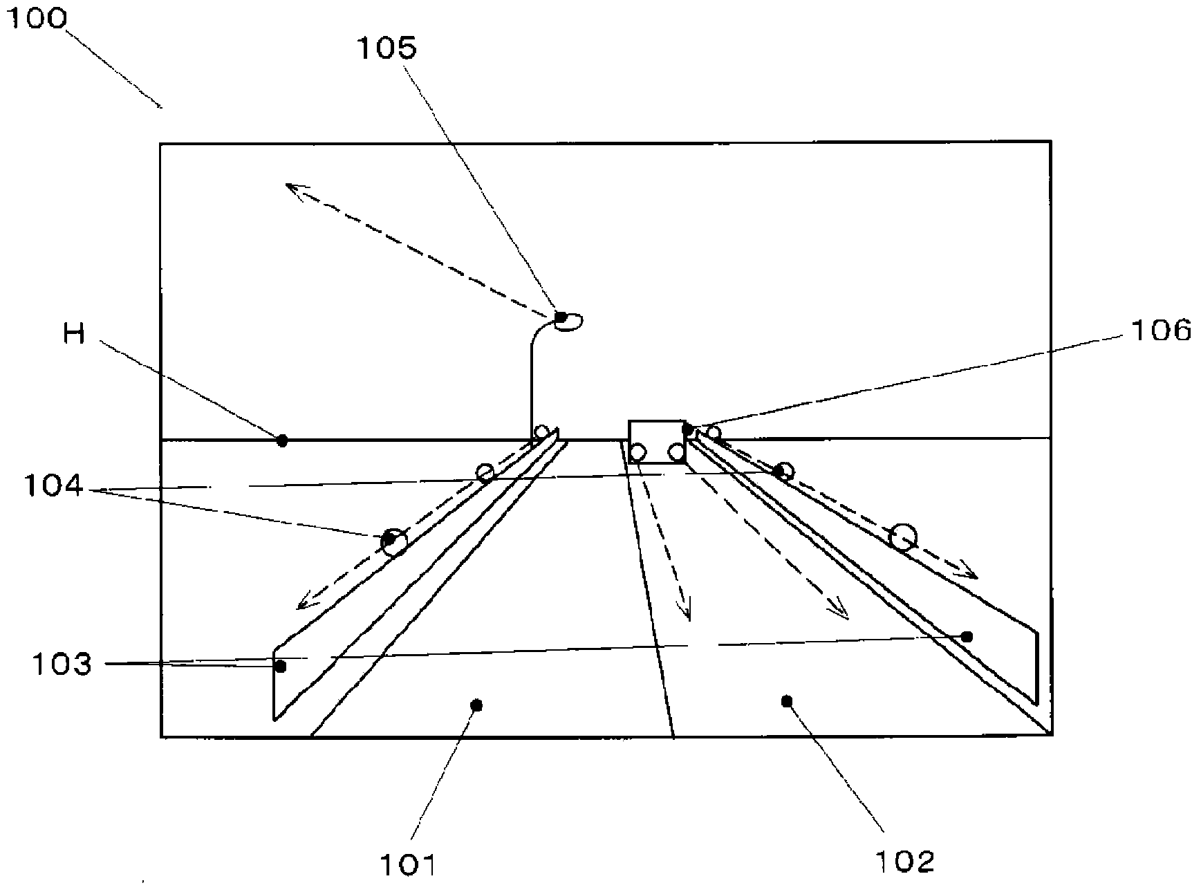
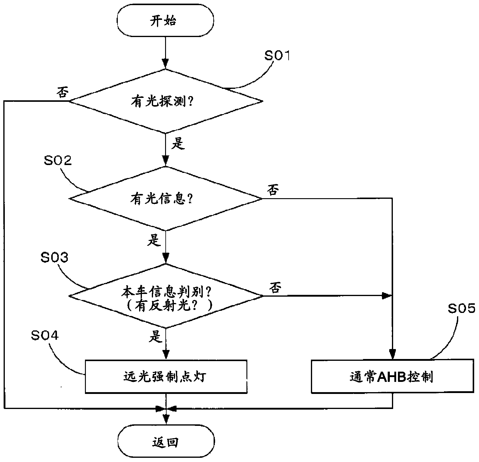
[0012] On the other hand, if the light source of the vehicle in front is mistaken for the reflected light of the headlights of the own vehicle, the vehicle in front will be directly illuminated with high beams, thereby causing it to be dazzled.

Method used


Image

  • Headlight control device
  • Headlight control device
  • Headlight control device

Examples


Embodiment

[0053] Next, an embodiment using the headlamp control device of the present invention will be described.

[0054] The headlamp control device of the embodiment is installed in the front of a car such as a car, for example, and controls the headlamps that illuminate a predetermined area in front of the vehicle.

[0055] figure 1 It is a block diagram showing the configuration of the headlamp control device of the embodiment.

[0056] like figure 1 As shown, the headlight control device 1 is configured to include a left headlight 11 , a right headlight 12 , a controller 20 , a headlight control unit 30 , a camera unit 40 , a travel information detection unit 50 and the like.

[0057] The left headlight 11 and the right headlight 12 are respectively arranged on the left and right sides of the front part of the vehicle body.

[0058] The left headlight 11 and the right headlight 12 can select high beams (beams for driving) that will be irradiated to the front of the vehicle to,...


PUM


Abstract

A headlight control device automatically switches a light distribution pattern of a headlight(11,12) for illumination ahead of a vehicle. The headlight control device including an imager(40) that sequentially takes images of a view ahead of the vehicle in a predetermined frame rate, an another-vehicle recognizer that recognizes a light source of another vehicle from each of the images sequentially taken by the imager, a light distribution controller(30) that switches the light distribution pattern according to a recognition result of the another-vehicle recognizer, and a signal provider(20) that provides a signal to illumination light of the headlight by causing the luminance of the headlight to change in a predetermined cycle. The another-vehicle recognizer recognizes, as reflected light of the headlight of the vehicle, a light source which is present within the image and of which luminance change is substantially similar to a luminance change of the signal.

Description

technical field [0001] The present invention relates to a headlamp control device which detects the situation in front of the own vehicle and automatically switches the light distribution type, and more particularly relates to a device which can recognize the reflected light of the headlamp of the own vehicle from other light sources. Background technique [0002] Generally, the headlights of vehicles such as automobiles can be switched between a driving beam (high beam) and a crossing vehicle beam (low beam), or can be turned off independently of the driving beam and the crossing vehicle beam. [0003] In recent years, it has been proposed to automatically switch from high beam to close when the situation ahead of the host vehicle is recognized by cameras and radars, and when glare (glare) is detected. Light switching function (automatic high beam function). [0004] As a prior art related to such automatic high beams, for example, Patent Document 1 describes the following...

Claims


Application Information

Patent Timeline
Patent Type & Authority Applications(China)
IPC IPC(8): B60Q1/14
CPCB60Q2300/144B60Q2300/3321B60Q2300/314B60Q2300/42F21S41/00B60Q1/143G06V20/584B60Q1/0023B60Q2300/41B60Q1/04B60Q1/08B60Q2300/054B60Q1/1423
Inventor 早川和裕青木勇人
Owner SUBARU CORP
Learn More