
Three-dimensional scanning system with rotary workbench

A rotating table and three-dimensional scanning technology, applied in the field of three-dimensional scanning, can solve the problems of unfavorable shooting image balance, large relative coordinate changes, and increased splicing difficulty, so as to improve convenience and authenticity, improve accuracy, and improve scanning sexual effect

Active Publication Date: 2014-12-31
日照坤元信息科技有限公司
View PDF4 Cites 14 Cited by
  • Summary
  • Abstract
  • Description
  • Claims
  • Application Information

AI Technical Summary

Problems solved by technology

[0004] Nowadays, the conversion of the shooting angle by the 3D scanner is realized by moving the support frame, which is not only labor-intensive and slow in moving speed, but also has a large change in relative coordinates, which is difficult to control, which is not conducive to the balance of the captured image and increases the difficulty of splicing

Method used


Image

  • Three-dimensional scanning system with rotary workbench
  • Three-dimensional scanning system with rotary workbench

Examples


Embodiment Construction

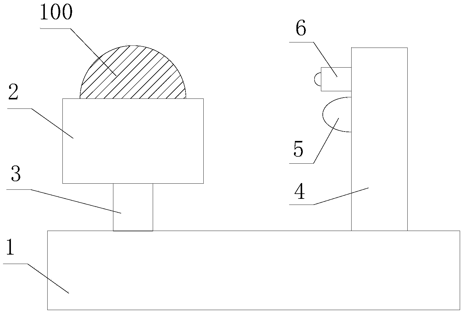
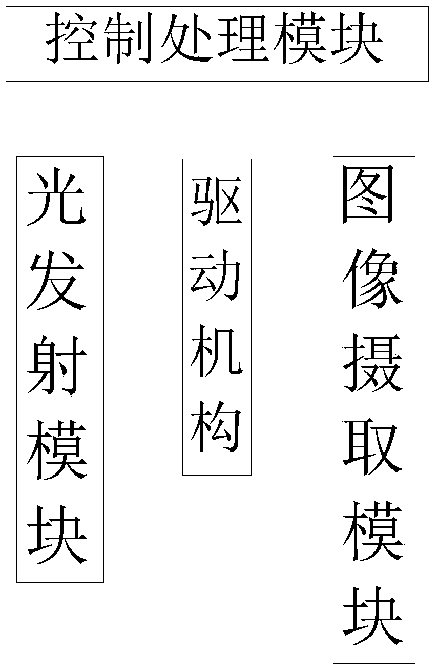
[0019] refer to figure 1 , figure 2 , a three-dimensional scanning system with a rotating table proposed by the present invention, including: a base 1, a table 2, a rotating shaft 3, a driving mechanism, a support frame 4, a light emitting module 5, an image capturing module 6 and a control processing module.

[0020] The workbench 2 is rotatably mounted on the base 1 through the rotating shaft 3 and is used to carry the scanning piece 100 , and the driving mechanism is used to drive the rotating shaft 3 to rotate.

[0021] The supporting frame 4 is installed on the base 1 , and the light emitting module 5 and the image capturing module 6 are both installed on the supporting frame 4 . The light emitting module 5 is used for projecting light to the scanning part 100 , and the image capturing module 6 is used for taking images of the scanning part 100 .

[0022] In this embodiment, the light emitting module 5 adopts a white light emitter to emit white light to avoid harm to t...


PUM


Abstract

The invention provides a three-dimensional scanning system with a rotary workbench. The three-dimensional scanning system with the rotary workbench comprises a base, a workbench, a spindle, a driving mechanism, a support frame, an optical transmitter module, an image shooting module and a controlling and processing module, wherein the workbench is rotatably installed on the base by the spindle and is used for bearing a scanned piece; the driving mechanism is used for driving the spindle to rotate; the support frame is installed on the base; the optical transmitter module and the image shooting module are both installed on the support frame; the optical transmitter module is used for projecting ray to the scanned piece; the image shooting module is used for shooting an image to the scanned piece; the controlling and processing module is used for converting image information into data information; the data information is operated to establish a data model; the controlling and processing module is respectively connected with the driving mechanism, the optical transmitter module and the image shooting module to control the driving mechanism, the optical transmitter module and the image shooting module to work. According to the three-dimensional scanning system with the rotary workbench, the scanned piece can automatically rotate to switch a shooting angle, the labor intensity is lowered, and scanning precision is improved.

Description

technical field [0001] The invention relates to the technical field of three-dimensional scanning, in particular to a three-dimensional scanning system with a rotating worktable. Background technique [0002] In the early days, most of the 3D measuring equipment in our country were three-coordinate measuring machines. This kind of equipment is characterized by single-point coordinate extraction, and the measurement of straight-line distance is acceptable. For curved surfaces and some soft rubber samples that are easily deformed, it cannot be done quickly and easily. Problem solved. Due to the continuous improvement of production technology, a large number of such measurement needs have prompted the advent of non-contact 3D scanners. The non-contact 3D scanner obtains the surface image of the sample through the principle of light reflection, and then analyzes the position information of each reflection point relative to the coordinate 0 through the analysis of the software t...

Claims


Application Information

Patent Timeline
Patent Type & Authority Applications(China)
IPC IPC(8): G01B11/24
Inventor 吕月林
Owner 日照坤元信息科技有限公司
Learn More