A method for splicing naked-eye 3D splicing walls

A splicing wall, 3D technology, applied in the optical field, to reduce the difficulty of splicing and facilitate transportation and installation.

Active Publication Date: 2016-03-16
NINGBO VISION DISPLAY TECH
View PDF4 Cites 0 Cited by
  • Summary
  • Abstract
  • Description
  • Claims
  • Application Information

AI Technical Summary

Problems solved by technology

[0012] The purpose of the present invention is to solve the problems existing in the splicing method of the traditional large display screen, and to provide a splicing method for naked-eye 3D splicing walls

Method used


Image

  • A method for splicing naked-eye 3D splicing walls
  • A method for splicing naked-eye 3D splicing walls
  • A method for splicing naked-eye 3D splicing walls

Examples


specific Embodiment approach 1

[0038] Specific embodiment one: the following combination Figure 5 to Figure 7 Describe this embodiment, a naked eye 3D video wall splicing method described in this embodiment, the method includes the following processes:

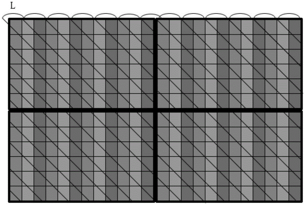
[0039] Step 1. Arrange N×M independent display modules in a matrix A = L 11 L 12 L 1 M L 21 L 22 L 2 ...

specific Embodiment approach 2

[0053] Specific implementation mode two: the following combination Figure 9 to Figure 11 Describe this implementation mode. This implementation mode will further explain the first implementation mode, and obtain the raster parameters α of N×M independent display modules as described in step two. nm and R nm , and the tuning parameter S nm The process is:

[0054] Step 21. Obtain an independent display module L 11 The grating parameter α 11 and R 11 , and set the independent display module L 11 The adjustment parameter S 11 = 0;

[0055] Get Standalone Display Module L 11 The grating parameter α 11 and R 11 The process is:

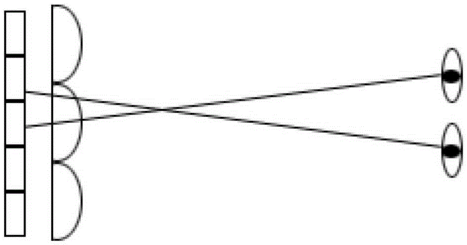
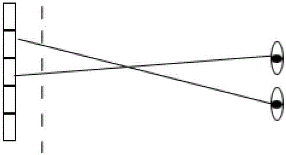
[0056] Module L will be displayed independently 11 Factory grating parameter α 0 and R 0 As the initial value of the raster parameters, with a weight of 0.001 to α 0 and R 0 Add or subtract until it is adjusted to be able to watch the independent display module L at the best viewing distance 11 When there are nine viewpoint images, the fol...

specific Embodiment approach 3

[0061] Specific implementation mode three: this implementation mode further explains implementation mode two, the best viewing distance is D±20cm, where D is according to the formula

[0062] D = a 2 tan ( arcsin ( n 0 sin ( src tan ( Q ( n 0 - 1 ) 8 ...


PUM


Abstract

A glasses-free 3D joint wall jointing method belongs to the optical field. The invention aims to solve a problem existing in a jointing method for a traditional large display screen. The method provided by the invention comprises: (1) N*M independent display modules are arranged according to a matrix pattern to form a joint wall, and each module is provided with four borders; (2) grating parameters and adjustment parameters of each module are obtained, so that the angle of a black-and-white test pattern displayed by each module is consistent; (3) a coordinate system is built by taking the left upper corner of the joint wall as an original point, steps (4)-(7) are performed, any one address (x,y) on the joint wall is traversed, and information of a color which should be displayed by a pixel at the address is determined; (4) whether the address (x,y) is in a border area is judged, step (5) is performed if the address (x,y) is in the border area, and step (6) is performed if the address (x,y) is not in the border area; (5) the address (x,y) does not call image information of a present frame; (6) a viewpoint NV belonging to the address (x,y) is obtained; and (7) according to the obtained viewpoint NV belonging to the address (x,y), the information of the color should be displayed by the pixel at the address (x,y) is obtained by adopting bilinear interpolation.

Description

technical field [0001] The invention relates to a large display screen splicing method, which belongs to the field of optics. Background technique [0002] The so-called autostereoscopic display technology means that the audience can freely and clearly watch the stereoscopic image on the screen with the naked eye at multiple positions within a large angle without any auxiliary equipment (such as polarized glasses, head-mounted display, etc.). Implementation methods are as follows: figure 1 The autostereoscopic display technology based on the lenticular grating shown and such as figure 2 The parallax barrier-based autostereoscopic display technology shown. Autostereoscopic display technology based on lenticular grating: the image plane of the liquid crystal screen is located on the focal plane of the lens, and the pixels of the image under each cylindrical lens are divided into several sub-pixel directions for projection, so the two eyes view the display screen from differ...

Claims


Application Information

Patent Timeline
Patent Type & Authority Patents(China)
IPC IPC(8): H04N13/00H04N13/04
Inventor 蒋香锋顾开宇
Owner NINGBO VISION DISPLAY TECH
Why Eureka
Try Eureka