Wiring terminal with pluggable pulling covers

A terminal, plug-in technology, applied in the direction of connection, multi-core cable end parts, parts of connection devices, etc., can solve the problems of reducing labor intensity, reducing wiring efficiency, accidental disconnection, etc., and achieve the wiring work. Simple and efficient construction

Inactive Publication Date: 2015-01-21
JIANGMEN KREALUX ELECTRICAL APPLIANCES
View PDF8 Cites 7 Cited by
  • Summary
  • Abstract
  • Description
  • Claims
  • Application Information

AI Technical Summary

Problems solved by technology

However, the structures of the existing terminal blocks are varied, and the wiring cannot be completed in one step. It is often necessary to disassemble the terminal block and use bolts, rivets, etc. to connect the wires to the terminal block. Wiring process and reduce the efficiency of wiring, increase labor intensity
And the wiring terminal is equipped with wires, it is necessary to take the wires off the wire from the wiring terminal, and it is necessary to disassemble the wiring terminal again, loosen fixing parts such as bolts, so that the wire is separated from the conductive sheet of the wiring terminal, which is very inconvenient.
Especially when the wiring of existing electrical appliances or electronic components needs to be connected through the cooperation of two terminals to realize the connection of hard wires and flexible wires or different numbers of strands, it is quite troublesome that these two termi

Method used


Image

  • Wiring terminal with pluggable pulling covers
  • Wiring terminal with pluggable pulling covers
  • Wiring terminal with pluggable pulling covers

Examples


Embodiment 1

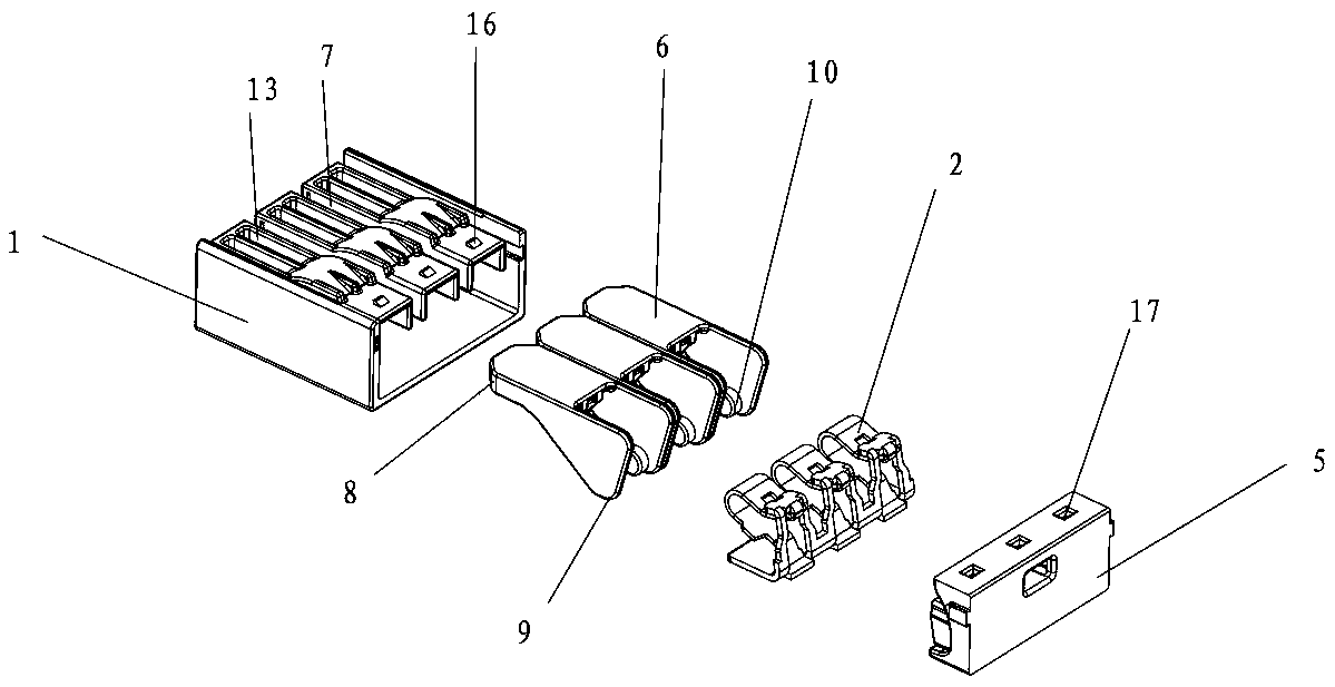
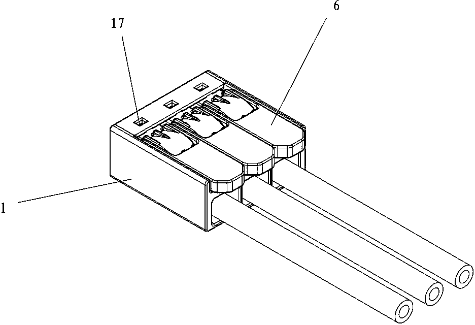
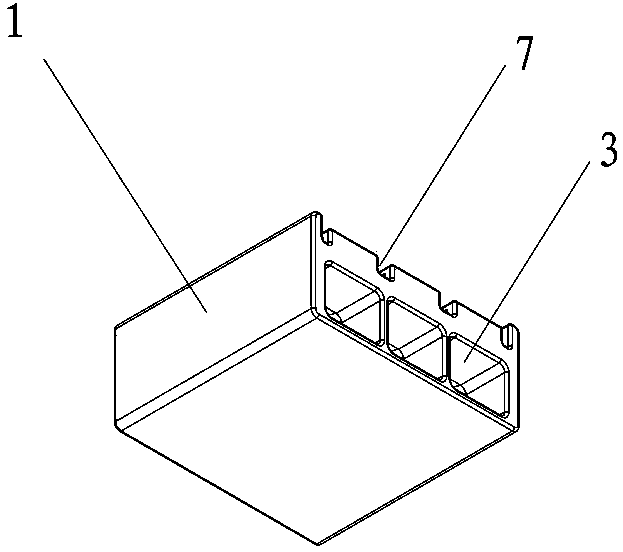
[0037] A cover plug-in terminal described in Embodiment 1 of the present invention, such as figure 1 , figure 2 , image 3 , Figure 4 , Figure 5 , Image 6 , Figure 7 , Figure 8 , Figure 9 , Figure 10 , Figure 11 , Figure 12 , Figure 13 , Figure 14 , Figure 15 , Figure 16 , Figure 17 , Figure 18 , Figure 19 , Figure 20 , Figure 21 , Figure 22 , Figure 23 , Figure 24 with Figure 25As shown, it includes an insulating housing 1 with an integrated structure and a cavity to form a hollow structure. The insulating housing is provided with a conductive metal piece 2 installed in the cavity. The front end of the insulating housing is provided with three corresponding conductive metal pieces. The plug-in port 3, the rear end of the insulating housing is provided with the installation port 4 corresponding to the conductive metal parts, and the conductive metal parts are installed into the insulating housing from the installation port, and also...


PUM


Abstract

The invention discloses a wiring terminal with pluggable pulling covers. The wiring terminal comprises an insulation shell. Conductive metal parts are arranged in the insulation shell, wire insertion openings are formed in the front end of the insulation shell, installation ports are arranged at the rear end of the insulation shell, and the conductive metal parts are mounted in the insulation shell from the installation ports. The wiring terminal further comprises a rear cover and the turnover pulling covers, the rear cover is installed in cooperation with the installation ports and the turnover pulling covers are arranged on the top of the insulation shell. At least two through groove seams penetrating into a containing cavity are formed in the top of the insulation shell, one end of each turnover pulling cover is a pulled end, the other end of each turnover pulling cover is a rotated end, protruding cylindrical raised heads are fixedly arranged below the end portion of each rotated end, the cylindrical raised heads of each rotated end are eccentrically deviated from the central axis of the end portion of the corresponding rotated end, and the bottom surface of each cylindrical raised head is horizontally aligned to the bottom surface of the containing cavity; each conductive metal part is provided with a metal bottom plate and an elastic clamping piece cocked from the corresponding metal bottom plate to form a cage shape, and the wire clamping end portion of each elastic clamping piece is downwards and can be matched with the corresponding metal bottom plate to clamp a wire metal insertion end; each cylindrical raised head is located between the corresponding elastic clamping piece and the side portion of the corresponding metal bottom plate.

Description

technical field [0001] The present invention relates to the technical field of a connection terminal structure, in particular to a plug-in connection terminal with a plug-in connection, and the connection and disconnection are all realized by flipping and removing the cover. Background technique [0002] As a connecting component of electronic components, electrical appliances, etc., terminal blocks can have the effect of wiring and energization, and realize the good connection function of wiring and energization. It is an important wiring component for electrical connection and connection between terminal and terminal. However, the structures of the existing terminal blocks are varied, and the wiring cannot be completed in one step. It is often necessary to disassemble the terminal block and use bolts, rivets, etc. to connect the wires to the terminal block. Wiring process and reduce the efficiency of wiring, increase labor intensity. And connecting terminal is equipped wi...

Claims


Application Information

Patent Timeline
IPC IPC(8): H01R13/629H01R11/11
CPCH01R13/629H01R11/11H01R13/62905
Inventor 饶小坡尹波青郭志杰
Owner JIANGMEN KREALUX ELECTRICAL APPLIANCES
Why Eureka
Try Eureka