Latch type wiring terminal

A terminal and plug-type technology, which is applied in the field of plug-type terminals, can solve the problems of reducing wiring efficiency, reducing labor intensity, and unstable wiring, etc., and achieves the effect of high construction efficiency and simple wiring work

Active Publication Date: 2014-07-30
JIANGMEN KREALUX ELECTRICAL APPLIANCES
View PDF5 Cites 8 Cited by
  • Summary
  • Abstract
  • Description
  • Claims
  • Application Information

AI Technical Summary

Problems solved by technology

However, the structures of the existing terminal blocks are varied, and the wiring cannot be completed in one step. It is often necessary to disassemble the terminal block and use bolts, rivets, etc. to connect the wires to the terminal block. Wiring process and reduce the efficiency of wiring, increase labor intensity
And the wiring terminal is equipped with wires, it is necessary to take the wires off the wire from the wiring terminal, and it is necessary to disassemble the wiring terminal again, loosen fixing parts such as bolts, so that the wire is separated from the conductive sheet of the wiring terminal, which is very inconvenient.
Especially when the wiring of existing electrical appliances or electronic components needs to be connected through the cooperation of two terminals to realize the connection of hard wires and flexible wi

Method used


Image

  • Latch type wiring terminal
  • Latch type wiring terminal
  • Latch type wiring terminal

Examples


Embodiment 1

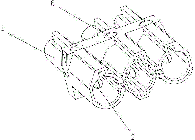
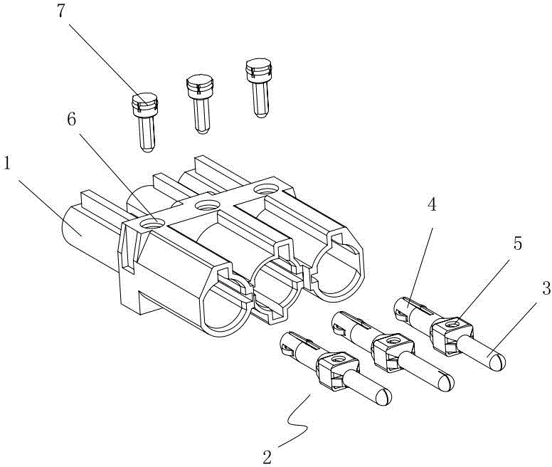
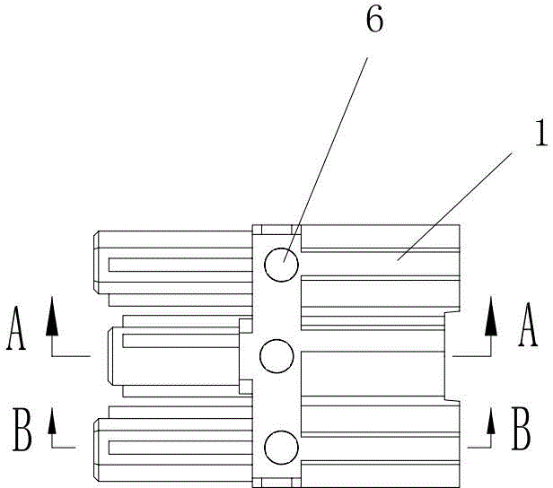
[0027] A plug-type terminal described in Embodiment 1, such as figure 1 , figure 2 , image 3 , Figure 4 , Figure 5 As shown, it includes an insulating housing 1 and a conductive metal insert 2 located in the insulating housing; as Figure 10 , Figure 11 , Figure 12 , Figure 13 As shown, one end of the conductive metal insert is provided with a pin 3, and the other end is provided with a socket 4; the conductive metal insert is provided with a first socket 5, and the insulating shell is provided with a second socket 6 corresponding to the position of the first socket; figure 2 , Figure 4 , Figure 5 , Figure 14 As shown, it also includes a plug connector 7 that passes through the second socket and the first socket in turn and can fix the conductive metal insert in the insulating housing; Figure 6 , Figure 7 , Figure 8 , Figure 9 As shown, the insulating housing is provided with the installation position of the plug socket 8 corresponding to the plug p...


PUM


Abstract

The invention discloses a latch type wiring terminal. The latch type wiring terminal comprises an insulation housing and a conductive metal plug-in disposed in the insulation housing. One end of the conductive metal plug-in is provided with a latch, and the other end is provided with a socket; the conductive metal plug-in is provided with a first insertion hole; the insulation housing is provided with a second insertion hole opposite to the first insertion hole in terms of position; the latch type wiring terminal further comprises a latch connecting piece which successively passes through the first insertion hole and the second insertion hole and can enable the conductive metal plug-in to be fixed in the insulation housing; and the insulation housing is provided with an installation position, which is corresponding to the latch, of a latch insertion hole, and an installation position, which is corresponding to the socket, of the socket insertion hole. During wiring, leads are riveted on an external latch or an external socket in advance, and then the external latch or the external socket are inserted to the corresponding socket or the corresponding latch inside the insulation housing, such that the external latch and the external socket form mutual installation with the socket and the latch in the insulation housing, and the wiring is fished; and the latch connecting piece can enable the conductive metal plug-in to be fixed in the insulation housing.

Description

technical field [0001] The invention relates to a plug-type terminal, in particular to a plug-type terminal which adopts plug-type and plug-in connection and can be disconnected quickly. Background technique [0002] As a connector for electronic components, electrical appliances, etc., the terminal block can play the role of wiring and energization. It is an important wiring component for electrical connection and connection between terminal blocks and terminal blocks. However, the structures of the existing terminal blocks are varied, and the wiring cannot be completed in one step. It is often necessary to disassemble the terminal block and use bolts, rivets, etc. to connect the wires to the terminal block. Wiring process and reduce the efficiency of wiring, increase labor intensity. And connecting terminal is equipped with conducting wire, needs lead wire to be taken off the line in connecting terminal, needs to dismantle connecting terminal again, unclamps fixtures such...

Claims


Application Information

Patent Timeline
IPC IPC(8): H01R13/02H01R13/627H01R13/629H01R13/639
CPCH01R13/42H01R13/111H01R13/64H01R2105/00
Inventor 饶小坡尹波青
Owner JIANGMEN KREALUX ELECTRICAL APPLIANCES
Why Eureka
Try Eureka