
A kind of LED dispensing packaging equipment
A packaging equipment and dispensing technology, applied in electrical components, circuits, semiconductor devices, etc., can solve problems such as adverse effects on processing accuracy and large overall impact on the workbench
- Summary
- Abstract
- Description
- Claims
- Application Information
AI Technical Summary
Problems solved by technology
Method used
Image

Examples
Embodiment Construction
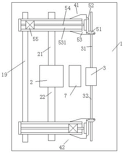
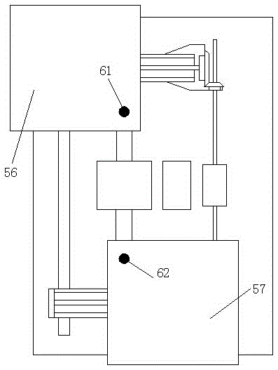
[0015] Attached below Figure 1-2 , the present invention will be described in detail.
[0016] A kind of LED dispensing and packaging equipment, comprising a frame 1, a front slide assembly 42, a rear slide assembly 41, a longitudinal drive motor 2 and a transverse drive motor 3, wherein the frame 1 is longitudinally provided with frame guide rails 19. The rear slide assembly 41 and the front slide assembly 42 are separately arranged on the frame 1 front and rear and are slidably matched with the frame guide rail 19; the longitudinal drive motor 2 and the horizontal drive The motors 3 are fixedly arranged on the frame 1 between the rear slide assembly 41 and the front slide assembly 42;
[0017] The front end of the longitudinal drive motor 2 is connected to the front longitudinal drive screw 22, the rear end is connected to the rear longitudinal drive screw 21, and the rear longitudinal drive screw 21 is connected to the wire on the rear slide assembly 41. The female threa...
PUM
 Abstract
Description
Claims
Application Information