
Bracket assembly and display device using same

A bracket assembly and display device technology, applied in the direction of machines/stands, supporting machines, mechanical equipment, etc., can solve the problems of undisclosed solutions, volume and weight not suitable for frequent movement, and display device shaking and instability

Inactive Publication Date: 2015-02-11
TOP VICTORY INVESTMENTS
View PDF5 Cites 0 Cited by
  • Summary
  • Abstract
  • Description
  • Claims
  • Application Information

AI Technical Summary

Problems solved by technology

However, unlike mobile devices, which can be placed and moved freely by users, desktop computers and their display devices are usually fixed in a specific position because their volume and weight are not suitable for frequent movement.
Generally speaking, the display device of a desktop computer may be placed near the back of the desktop, about 30 centimeters or more away from the user. The arm is stretched, even hanging in the air, causing inconvenience in use
[0003] Moreover, the support assembly used in the display device of the existing desktop computer generally only considers the need to support the display screen, but does not properly consider the additional horizontal stress that the display screen needs to bear during the touch operation (use or click on the screen), so when the user is performing a touch operation, it may cause the display device to vibrate and become unstable.
From this point of view, the existing display device, including the display screen and the bracket assembly for supporting the display screen, does not disclose a further solution

Method used


Image

  • Bracket assembly and display device using same
  • Bracket assembly and display device using same
  • Bracket assembly and display device using same

Examples


Embodiment Construction

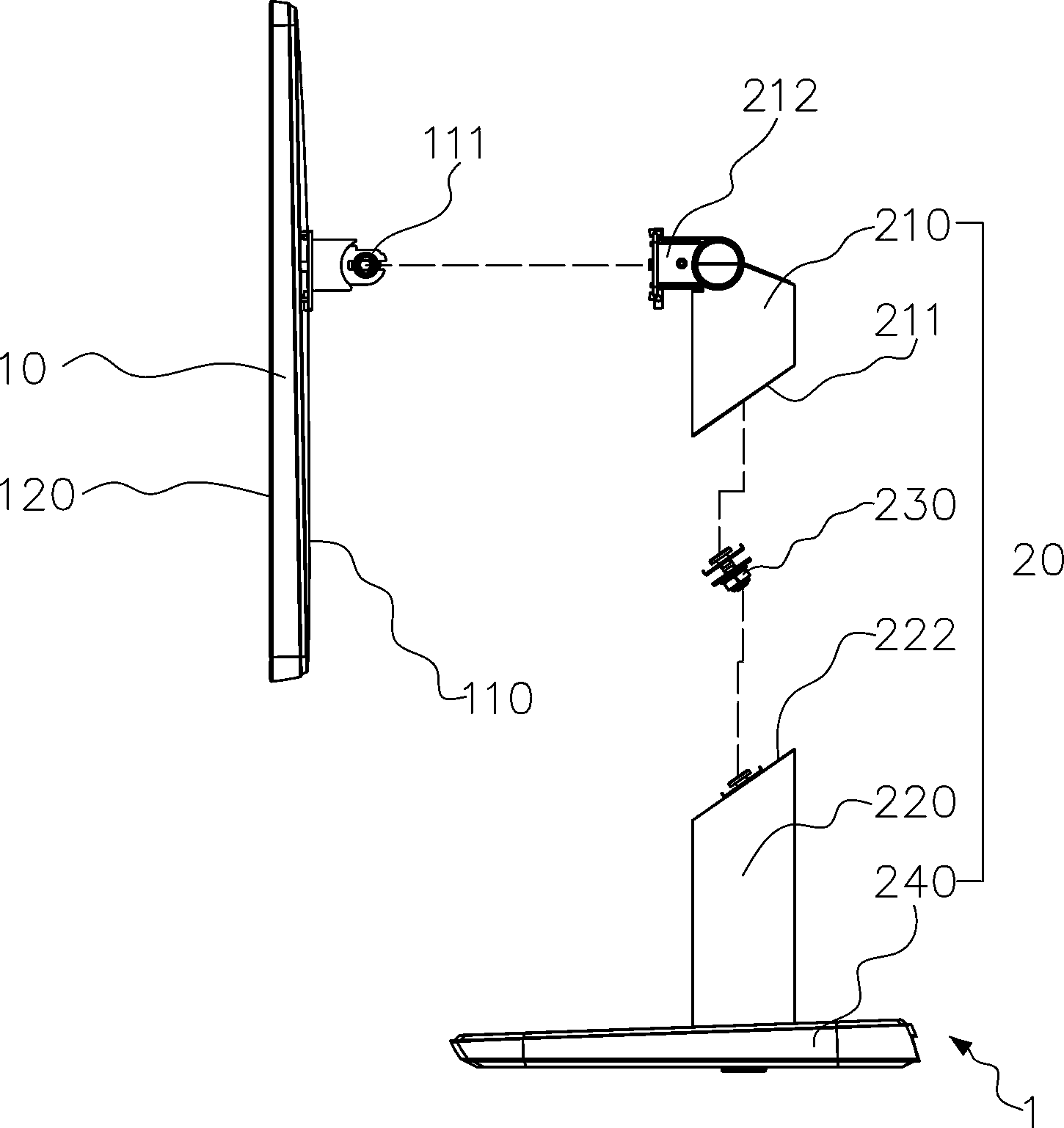
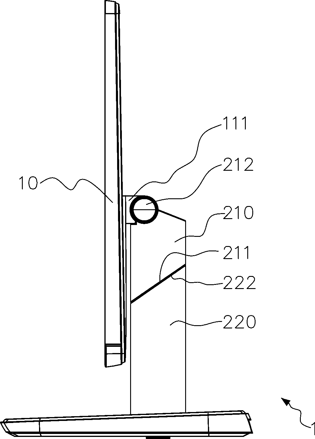
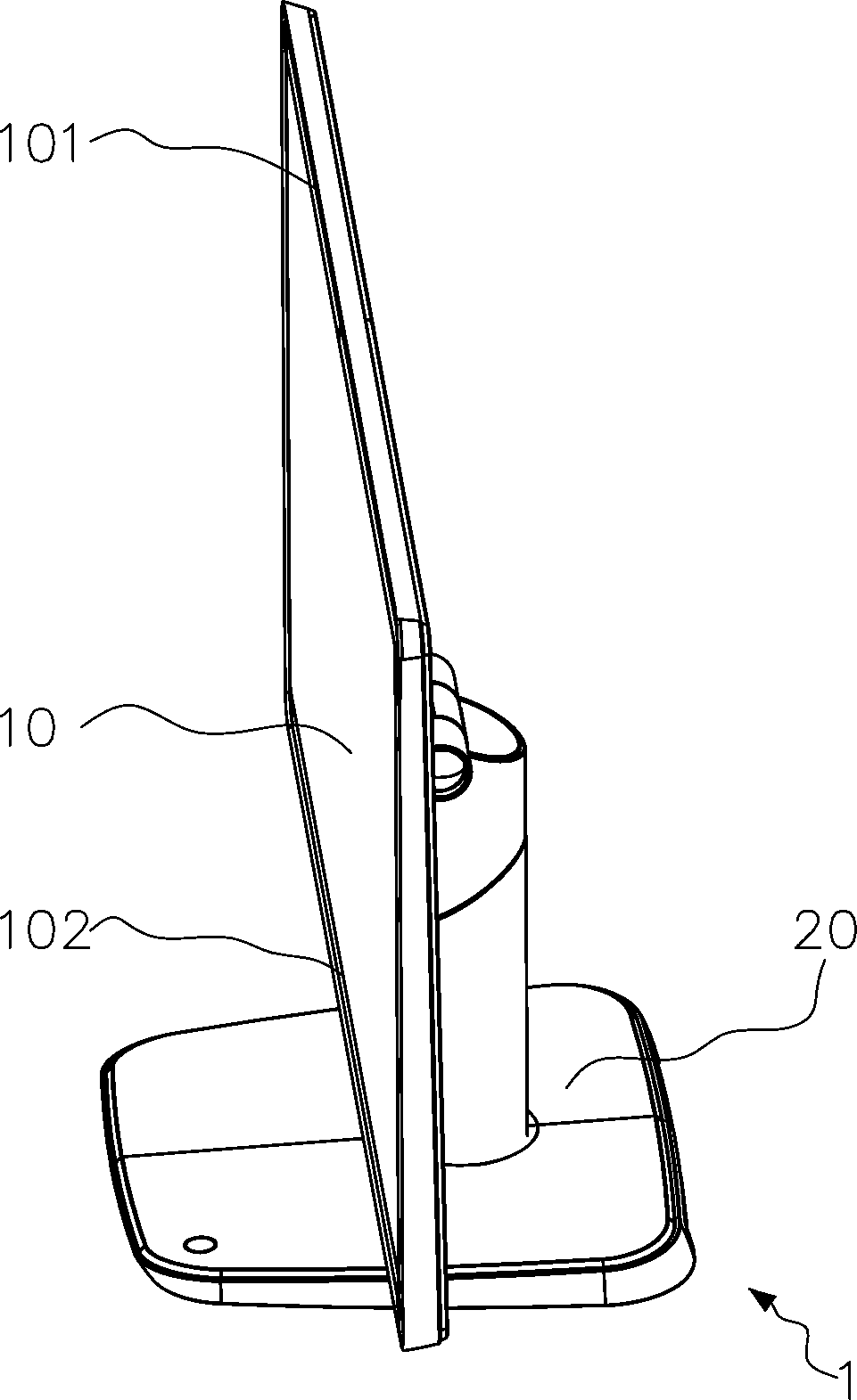
[0037] see figure 1 , figure 1 It is an exploded view of an exemplary embodiment of a display device, and the display device 1 includes a display screen 10 and a bracket assembly 20 . The display screen 10 has an opposite back shell 110 and a display surface 120, and the back shell 110 is provided with a first connection portion 111, wherein the first connection portion 111 can be fixed to the Video Electronics Standards Association (Video Electronics Standards Association) of the back shell 110. Association, VESA) holes, or the first connecting portion 111 can also be integrally formed with the back shell 110 . The bracket assembly 20 includes a bracket (not labeled), the bracket includes a first body 210 and a second body 220 , and the bracket assembly 20 further includes a pivot portion 230 and a base 240 . One end of the first body 210 has a first slope 211 , and the end of the first body 210 away from the first slope 211 further has a second connection portion 212 .

...


PUM


Abstract

The invention relates to a bracket assembly and a display device using the same. A display screen (10) is provided with a first connecting part (111); the bracket assembly (20) comprises a bracket and a pivoting part (230); the bracket is provided with a first body (210) and a second body (220), the first body is provided with a first inclined surface (211) and a second connecting part (212) pivoted with the first connecting part, the second body is provided with a second inclined surface (222), and the first inclined surface corresponds to the second inclined surface and is adjacent to the second inclined surface; one end of the pivoting part is connected with the first inclined surface, the other end of the pivoting part is connected with the second inclined surface, the first inclined surface and the second inclined surface can relatively pivot through the pivoting part, and associatively, the first body and the second body can relatively pivot. According to the bracket assembly and the display device, the use states of the bracket assembly and the display device can be changed according to user demands, so that the bracket assembly and the display device are relatively suitable for touch operation of a user.

Description

technical field [0001] The invention relates to a bracket assembly and a display device using the bracket assembly; in particular, it relates to a rotatable bracket assembly and a display device using the bracket assembly. Background technique [0002] The current touch technology is becoming more and more mature. In addition to mobile devices (such as smart phones or tablet computers) that are generally equipped with touch screens, the proportion of display devices used in desktop computers that are equipped with touch screens is also increasing. In addition, the operating system of the existing desktop computer has also set the touch control as a normal operation, and it can be predicted that in the near future, the display device of the desktop computer equipped with a touch screen will become the mainstream. However, unlike a mobile device that can be placed and moved freely by the user, a desktop computer and its display device are usually fixed at a specific location b...

Claims


Application Information

Patent Timeline
IPC IPC(8): F16M11/06F16M11/18
Inventor 江奕廷林英任蔡宇宏
Owner TOP VICTORY INVESTMENTS
Learn More