
Flexible electronic device

A technology for electronic devices and fixing parts, which is applied to identification devices, electrical equipment shells/cabinets/drawers, electrical components, etc., which can solve problems such as inapplicability to delicate operations, soreness and fatigue, lack of arm support, etc., to achieve a good user experience Effect

Active Publication Date: 2020-11-20
COMPAL ELECTRONICS INC
View PDF12 Cites 0 Cited by
  • Summary
  • Abstract
  • Description
  • Claims
  • Application Information

AI Technical Summary

Problems solved by technology

However, the existing touch method suspended on the desktop is prone to soreness and fatigue due to the lack of support of the arm during long-term touch operations
In addition, the touch functions of existing display screens are limited to simple touch operations, and are not suitable for fine operations such as drawing and writing.

Method used


Image

  • Flexible electronic device
  • Flexible electronic device
  • Flexible electronic device

Examples


Embodiment Construction

[0068] Reference will now be made in detail to the exemplary embodiments of the present invention, examples of which are illustrated in the accompanying drawings. Wherever possible, the same reference numbers will be used in the drawings and description to refer to the same or like parts.

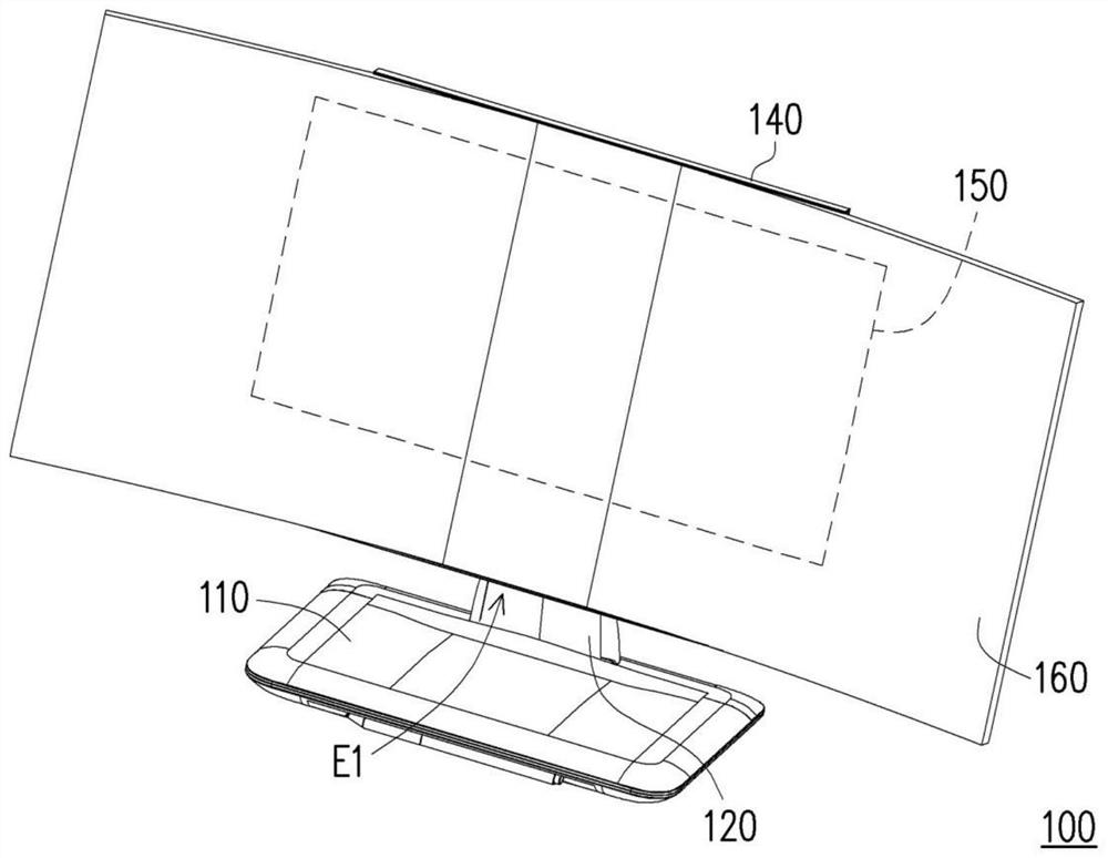
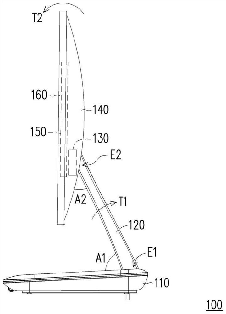
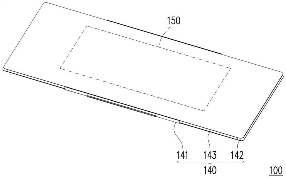
[0069] Figure 1A It is a three-dimensional schematic diagram of a curved surface mode of a flexible electronic device according to an embodiment of the present invention. Figure 1B Yes Figure 1A A schematic side-view plan view of the flexible electronic device of . Figure 1C Yes Figure 1A A three-dimensional schematic plan view of the flexible electronic device of . Figure 1D Yes Figure 1C A schematic side-view plan view of the flexible electronic device of . Figure 1E Yes Figure 1B Component exploded perspective view of a single pivot module of .

[0070] refer to Figure 1A to Figure 1D In this embodiment, the flexible electronic device 100 is, for example, a simple display...


PUM


Abstract

A flexible electronic device includes: a base; a supporting plate having a first end pivotally connected to the base, and a second end; two pivot modules disposed at the second end; a bearing frame having a fixed part connected to the two pivot modules, and two curved parts connected to the fixed part; a bending mechanism disposed on the fixed part and the two curved parts and connected to the pivot modules; and a flexible panel disposed on the bearing frame and covering the bending mechanism. When the flexible electronic device is switched to a curve mode, the bending module drives the two curved parts to stretch with respect to the fixed part to bend the flexible panel. When the flexible electronic device is switched to a flat mode, the bending module drives the two curved parts to moveclose to the fixed part to flatten the flexible panel.

Description

technical field [0001] The present invention relates to an electronic device, in particular to a flexible electronic device that can be switched between a curved surface mode and a planar mode. Background technique [0002] Existing electronic displays are mainly used to display images, characters or videos converted from numbers to signals. This type of electronic display is suitable for TVs, desktop computers, digital billboards, or portable electronic devices such as tablet computers, notebook computers, and smart phones. Most of the existing display screens have touch functions to replace An existing physical button. Taking a desktop computer as an example, the display screen is usually connected to a support structure perpendicular to the desktop, so that the display screen is suspended on the desktop and faces the user. Touch the screen. However, the existing touch control method suspended on the desktop is prone to soreness and fatigue due to the lack of support of...

Claims


Application Information

Patent Timeline
Patent Type & Authority Applications(China)
IPC IPC(8): G09F9/30
CPCG09F9/301G06F1/1601G06F2200/1612G06F1/1652F16M11/10F16M11/2021F16M11/38F16C11/04H05K5/0226H05K5/0017G06F1/1681G06F1/1641
Inventor 詹承学蓝伟豪
Owner COMPAL ELECTRONICS INC
Learn More