Structure of direct type backlight module with high uniform emitting light

a backlight module and direct type technology, applied in the direction of instruments, lighting and heating apparatus, planar/plate-like light guides, etc., can solve the problems of high radiation, high power consumption, blinking, etc., to save fabrication costs, increase light diffusion, and reduce total reflection

Active Publication Date: 2007-05-08
ENTIRE TECH CO LTD
View PDF6 Cites 23 Cited by
  • Summary
  • Abstract
  • Description
  • Claims
  • Application Information

AI Technical Summary

Benefits of technology

[0008]The primary object of the present invention is to provide a structure of direct type backlight module with high uniform emitting light, wherein using a structure of diffusing plate to increase light diffusion, transmission rate and save fabrication cost. There are plural lenticular lens on the surface of entrance facet of said diffusing plate and the interval two lenticular lens of said plural lenticular lens is half interval of two light source of plural light source. Moreover, the location of said lenticular lens is set against the center of light source to reduce total reflection at wide angle.
[0009]The secondary object of the present invention is to provide a structure of direct type backlight module with high uniform emitting light, wherein said lenticular lens is set against the center of light source. The curvature of said lenticular lens is increasing while being away from light source. While the curvature of said lenticular lens is enlarged, the effect of light scatter is reduced and the purpose of uniformity is implemented.
[0010]Another object of the present invention is to provide a structure of direct type backlight module with high uniform emitting light, wherein provides a design of lenticular lens for diffusing plate. The lenticular lens of the present invention is against center of lamp to scatter light of said lamp area. Location is farther away from lamp, the curvature of said lenticular lens is larger, then the effect of light scatter is reduced and the purpose of uniformity is implemented. Design of another lenticular lens also focuses on the lamp location and distance and are set compound. Each set of lenticular lens is against the CCFL location to fit the effect of design of lenticular lens. The inclined light can be refracted through the angle of microstructure surface at entrance facet, but more distance location can be resulted in total refraction due to large inclined angle, then reducing the transmission light of light source and influencing the uniformity, finally reducing total reflection of wide angle. Except lenticular lens, diffusion plate itself contains sufficient light dispersant can make the light scattered and result in uniformity.

Problems solved by technology

Besides, some defects of conventional CRT TV are high power consumption, high radiation, blinking, and heavy weight.
Side type backlight source cannot provide high brightness and uniform light on the application of large-size liquid crystal monitors, due to being influenced by lamp tubes and light transmission distance.
Although the diffusion efficiency of early diffusing plate fits the requirement, the light transmission ratio and uniformity are still not good for display application, whose defect is the insufficient brightness.
Although transmission rate has increased in a range of from 50 to 70%, the transmission rate is not satisfied by the customers as high criteria product.
The vestige of CCFL can not be uniformed by diffusing plate, therefore, 1 to 2 diffuser put at the emitting facet of diffusing plate to achieve the effect of light scattering again which resulted in a range of from 5 to 10% light energy loss, then accommodating to prism sheet to bring light and counterbalance the loss.
Finally, the purpose of thin and lightweight backlight module can be implemented but resulted in huge increment of cost and lessening the visible angle of TV.
In order to increase the effect of light scattering, the light dispersant is added into said diffusing plate, but the price of light dispersant is very expensive.

Method used


Image

  • Structure of direct type backlight module with high uniform emitting light
  • Structure of direct type backlight module with high uniform emitting light
  • Structure of direct type backlight module with high uniform emitting light

Examples


embodiment 1

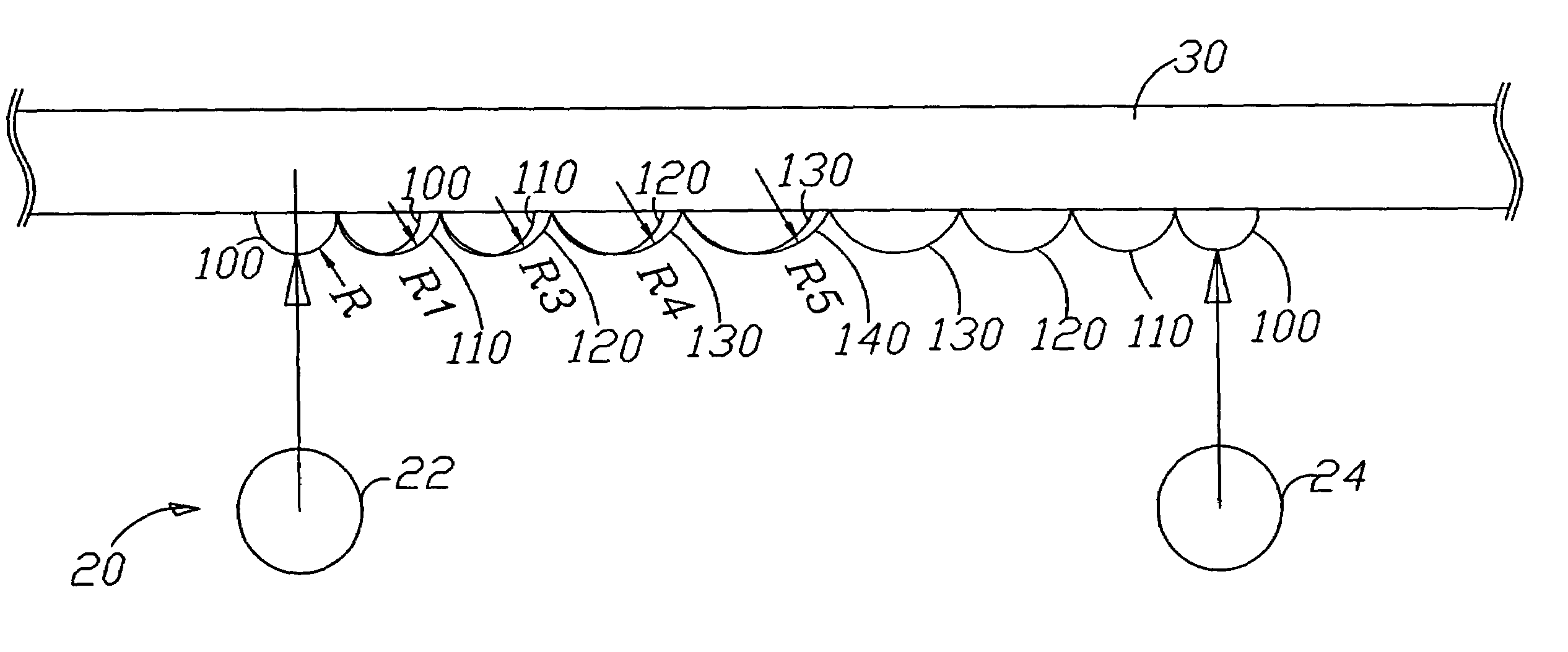
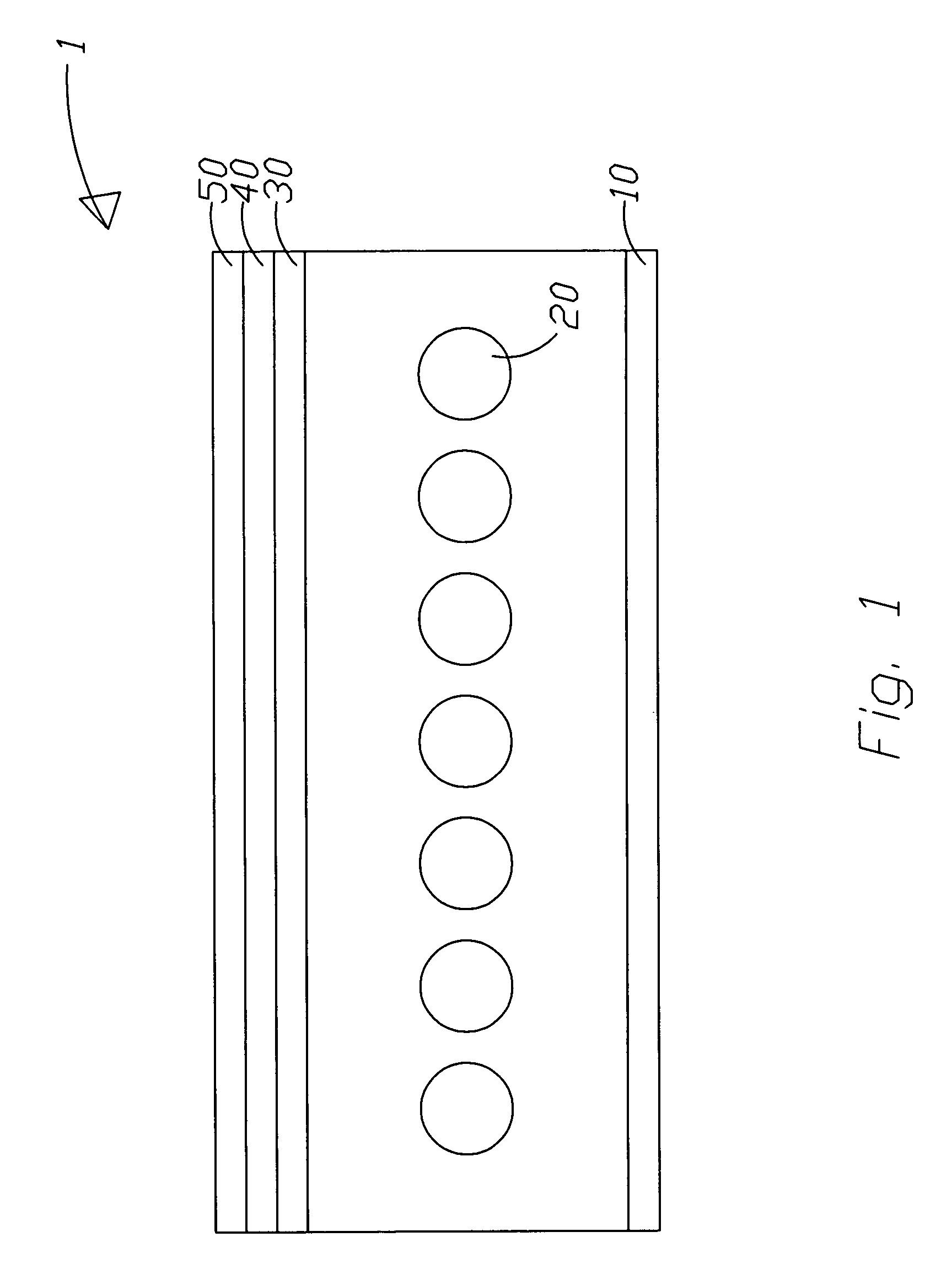
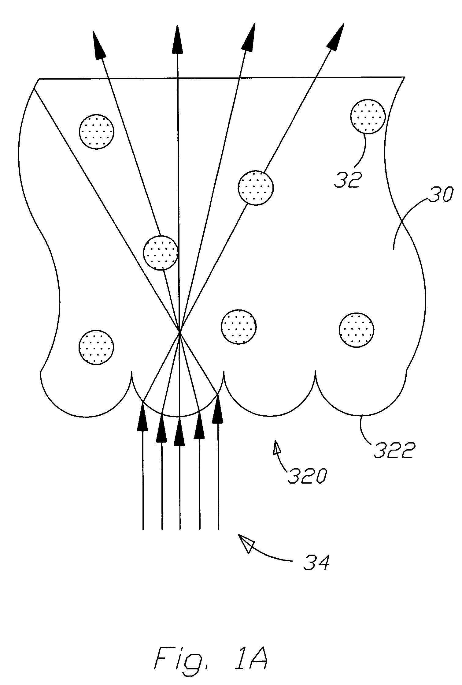
[0032]Lenticular lens is formed by using UV resin on the surface of entrance facet at the flat diffusing plate and then compared to conventional flat diffusing plate. The interval period of lenticular lens is 0.2 mm and the radius of curvature of lenticular lens is 0.2 mm, and the interval of lamp is 30 mm, the area of lenticular lens and none lenticular lens are equal whose length and width are 15 mm and interlaced as FIG. 2A. After forming lenticular lens are cut into proper figure and set at the direct type CCFL light source and the center of which aims to lamp location. After measuring, the result is shown as FIG. 3. Horizontal axis means distance and vertical axis means luminance intensity, the distribution of luminance intensity of none lenticular lens of flat diffuser on the module is not uniform. And lenticular lens of diffuser formed on the surface can achieve better diffusion effect and uniformity.

[0033]The present invention modifies light diffusion through changing curvat...


PUM

PropertyMeasurementUnit
weightaaaaaaaaaa
brightnessaaaaaaaaaa
widthaaaaaaaaaa

Abstract

A structure of direct type backlight module with high uniform emitting light explores a design of lenticular lens of diffusing plate. The lenticular lens is against the central location of light source, where the light of lamp is scattered and the curvature of said lenticular lens far away light source is enlarged, then to reduce the scatter effect and achieve uniformity. The other lenticular lens also can be designed for light location and distance. Each lenticular lens is against light location, and incident light can be reflected through the angle of microstructure surface at the entrance facet, but farther location can be resulted in total refraction due to large inclined angle, and diminishing the transmission light of light source then influencing the uniformity, finally reducing total reflection of wide angle.

Description

BACKGROUND OF THE INVENTION[0001]1. Field of the Invention[0002]The present invention relates to a structure of direct type backlight module with high uniform emitting light, which emphasizes on a direct type backlight module with high efficiency of light diffusion and transmission and low-cost diffusing plate.[0003]2. Description of the Related Art[0004]With the increment of HDTV, DVD player and Digital TV requirement, consumers are more and more concerned about the image quality of television. Besides, some defects of conventional CRT TV are high power consumption, high radiation, blinking, and heavy weight. Therefore, new generation display device having high solution in different monitors competition during these years has gradually placed CRT. Liquid crystal display with potential display technology has been always highly concerned for new generation display. The manufacturers in Japan, Taiwan and Korean are devoted into LCD technology research and adopting large-scale producti...

Claims


Application Information

Patent Timeline
Patent Type & Authority Patents(United States)
IPC IPC(8): F21V5/00F21V8/00G02B6/00G02F1/1335
CPCG02B6/003G02B6/0051G02B6/0041G02B6/0065
Inventor WANG, JYH HORNGCHANG, JEN-HUAILI, KAI-HSIN
Owner ENTIRE TECH CO LTD
Why Eureka
Try Eureka