A transmission line insulator r-shaped electromagnetic signal transmitting pin

An electromagnetic signal and insulator technology, applied in the field of electric power, can solve the problems of easy falling off of pins, safety accidents, and inability to perceive pins, and achieve the effect of not easily falling off

Active Publication Date: 2017-01-04
HULUDAO POWER SUPPLY COMPANY OF STATE GRID LIAONING ELECTRIC POWER +1
View PDF7 Cites 0 Cited by
  • Summary
  • Abstract
  • Description
  • Claims
  • Application Information

AI Technical Summary

Problems solved by technology

[0002] The existing transmission line insulators usually use pins to lock each other. Due to the influence of wind, the pins are easy to fall off. After the pins fall off, people cannot perceive them. Therefore, it is easy for the insulators to separate from each other, causing the power line to fall, causing power failure or Occurrence of security incidents
The pins currently used are straight and easy to fall off

Method used


Image

  • A transmission line insulator r-shaped electromagnetic signal transmitting pin
  • A transmission line insulator r-shaped electromagnetic signal transmitting pin
  • A transmission line insulator r-shaped electromagnetic signal transmitting pin

Examples


Embodiment Construction

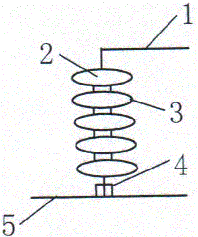
[0018] As shown in the figure, the cross arm 1 is connected to each other through pairs of upper insulators 2 and lower insulators 3 and a transmission line 5 is suspended.

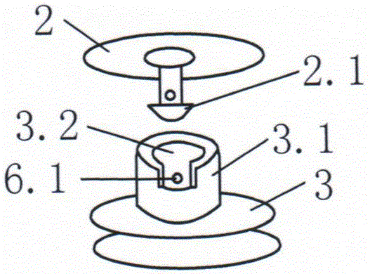
[0019] A locking nail 2.1 is installed in the middle hole of the upper insulator, a connecting column 3.1 is arranged on the upper part of the lower insulator, a connecting hole 3.2 is arranged in the connecting column, a pin hole 6.1 is arranged laterally on the wall of the connecting hole, and a locking nail is also provided There is a pin hole corresponding to the wall of the connection hole, and a pin 6 is inserted therein.

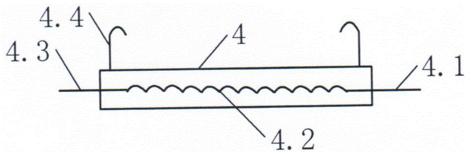
[0020] The pin structure is R-shaped, and the electromagnetic signal transmitter 6.2 is arranged on the pin.

[0021] In the electromagnetic signal transmitter, an induction coil 6.22 is connected through a power input line 6.21, and an electromagnetic induction secondary coil 6.23 is installed at a position opposite to the induction coil. Electromagnetic wave emitters 6.25.

...


PUM


Abstract

The invention proposes an R-shaped electromagnetic signal transmitting pin of a transmission line insulator. The cross arm is connected with each other through the pair of upper insulator and lower insulator and suspends the transmission line. A pin is arranged in the middle hole of the upper insulator, a connecting column with a connecting hole is arranged on the upper part of the lower insulator, and a pin hole is arranged on the wall of the connecting hole, and a pin is inserted therethrough. The pin structure is R-shaped, and an electromagnetic signal transmitter is arranged on the pin. An electromagnetic induction generator equipped with an induction coil is hung between the transmission line and the bottom insulator through an insulating hook. One end of the induction coil is connected to the ground wire, and the other end is used as a power output line. Interspersed pin circuit connection. A signal receiving display corresponding to each group of insulator pins is provided on the hand-held remote detector. The invention can monitor the position state of pins in time. It is suitable for application as a device for monitoring the pins of insulators on transmission lines.

Description

technical field [0001] The invention provides an accessory in the field of electric power, specifically an R-shaped electromagnetic signal transmitting pin of an insulator for a power transmission line. Background technique [0002] The existing transmission line insulators usually use pins to lock each other. Due to the influence of wind, the pins are easy to fall off. After the pins fall off, people cannot perceive them. Therefore, it is easy for the insulators to separate from each other, causing the power line to fall, causing power failure or occurrence of security incidents. The existing used pins are straight and easy to fall off. Contents of the invention [0003] In order to be able to monitor whether the pin exists, the present invention provides an R-shaped electromagnetic signal transmitting pin of the transmission line insulator. The pin adopts an R shape, and an electromagnetic signal transmitter is arranged on the pin. The induction current generated by th...

Claims


Application Information

Patent Timeline
Patent Type & Authority Patents(China)
IPC IPC(8): H02G7/00H02J50/20
Inventor 刘胜友张乐军贺树平张威才源贺鹏辉孙涛赵广忠韩汝军李志涛王根付帅邴冰天金宇静
Owner HULUDAO POWER SUPPLY COMPANY OF STATE GRID LIAONING ELECTRIC POWER
Why Eureka
Try Eureka